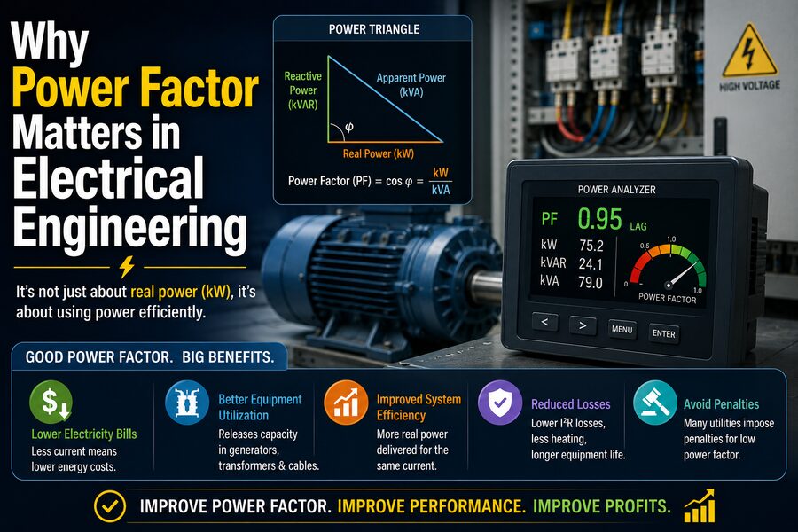

In alternating-current electrical systems, the amount of current flowing through a wire does not always tell you how much useful work is actually being performed. Motors, transformers, fluorescent lighting, power supplies, and many industrial machines can draw current that is partly out of phase with the voltage supplying them.
This creates an important electrical quantity called power factor.
Power factor is a measure of how effectively electrical power is being converted into useful work. A system with a high power factor uses current efficiently, while a system with a low power factor requires more current to deliver the same amount of useful power.
That extra current matters because it increases losses in cables, transformers, generators, switchgear, and utility networks. It can also reduce the amount of equipment capacity available for useful loads.
For this reason, power factor is especially important in industrial facilities, commercial buildings, power distribution systems, renewable-energy installations, and large motor-driven operations. ⚙️⚡
Understanding power factor helps electrical engineers design systems that are safer, more efficient, and more economical.
🔌 What Is Power Factor?
Power factor is usually defined as:
Power Factor = Real Power / Apparent Power
or:
PF = P / S
where:
- P = real power, measured in watts or kilowatts
- S = apparent power, measured in volt-amperes or kilovolt-amperes
Power factor is usually expressed as a decimal between 0 and 1.
For example:
PF = 1.0
means all the apparent power is being converted into real power.
A power factor of:
PF = 0.8
means only part of the apparent power corresponds to useful real power.
The closer the power factor is to 1, the more efficiently the electrical current is being used.
💡 What Is Real Power?
Real power is the electrical power that performs useful work.
Examples include:
- Turning a motor shaft
- Heating an electric furnace
- Producing light
- Operating electronics
- Driving pumps and compressors
Real power is measured in:
Watts (W) or kilowatts (kW)
If a motor consumes 50 kW of real power, that 50 kW is the portion contributing to useful energy conversion plus internal losses.
🔄 What Is Reactive Power?
Many AC devices contain inductors or capacitors.
These components temporarily store electrical energy and then return it to the circuit.
The power associated with this repeated exchange is called reactive power.
Reactive power is measured in:
volt-amperes reactive (VAR)
or:
kilovolt-amperes reactive (kVAR)
Reactive power does not directly produce useful mechanical work in the same way real power does.
However, it is often necessary for equipment such as motors and transformers because magnetic fields require reactive energy.
This makes reactive power important even though it does not directly appear as useful output.
📦 What Is Apparent Power?
Apparent power represents the total electrical loading placed on the system.
It combines the effects of real and reactive power.
It is measured in:
volt-amperes (VA)
or:
kilovolt-amperes (kVA)
Electrical equipment such as:
- Transformers
- Generators
- UPS systems
- Cables
is often rated in terms of VA or kVA because these components must carry the total current, not only the portion associated with useful real power.
📐 The Power Triangle
Real power, reactive power, and apparent power can be visualized using a power triangle.
The horizontal side represents:
Real Power (P)
The vertical side represents:
Reactive Power (Q)
The diagonal represents:
Apparent Power (S)
The relationship is:
S² = P² + Q²
For sinusoidal systems, power factor is related to the phase angle:
PF = cos φ
where φ is the angle between voltage and current.
This geometric relationship makes it easier to understand why larger reactive power increases apparent power.
🌊 Why Voltage and Current Can Become Out of Phase
In a purely resistive load, such as an ideal electric heater, voltage and current rise and fall together.
They are essentially in phase.
This produces a power factor close to 1.
Inductive loads behave differently.
Devices such as:
- Induction motors
- Transformers
- Ballasts
- Solenoids
create magnetic fields.
In an ideal inductor, current lags voltage by 90 degrees.
Real electrical devices are not perfect inductors, but their inductive behavior causes current to lag voltage.
This phase difference lowers power factor.
🧲 Why Motors Often Cause Low Power Factor
Electric motors are among the most common causes of poor power factor in industrial facilities.
An induction motor requires magnetizing current to create the magnetic field needed for operation.
Even when the motor is lightly loaded, it may still draw a significant magnetizing current.
As a result, a lightly loaded motor can have a particularly poor power factor.
For example, a motor operating near full mechanical load may have a relatively good power factor.
The same motor operating at only a small fraction of its rated load may have a considerably lower power factor.
This is one reason engineers try to avoid oversizing motors unnecessarily.
⚡ Why Low Power Factor Means More Current
One of the most important consequences of low power factor is increased current.
For a simplified single-phase AC system:
P = V × I × PF
Therefore:
I = P / (V × PF)
Suppose a load requires:
10 kW
at:
230 V
If power factor is 1.0:
I ≈ 10,000 / 230 = 43.5 A
If power factor falls to 0.5:
I ≈ 10,000 / (230 × 0.5) = 87 A
The current nearly doubles.
The useful power has not increased.
The cable simply has to carry much more current to deliver the same 10 kW.
🔥 Higher Current Means Higher Cable Losses
Electrical conductors have resistance.
Power lost as heat in a conductor is approximately:
P_loss = I²R
This equation is extremely important.
Because current is squared, increasing current causes losses to rise rapidly.
If current doubles:
I² becomes four times larger.
Therefore, poor power factor can significantly increase resistive heating in cables and transformers.
This wastes energy and can increase operating temperature.
🧯 Low Power Factor Can Require Larger Equipment
Since electrical infrastructure must carry current, poor power factor can require larger equipment.
For example, engineers may need:
- Larger cables
- Larger transformers
- Higher-rated switchgear
- Larger generators
- Higher-capacity UPS systems
Imagine a facility using 800 kW.
At a power factor of 1.0, its apparent power is:
800 kVA
At a power factor of 0.8:
S = 800 / 0.8 = 1,000 kVA
The facility still uses 800 kW of real power, but its electrical infrastructure must now handle about 1,000 kVA.
That difference can be significant.
🏭 Why Utilities Care About Power Factor
Electric utilities must generate and transmit enough current to supply customers.
Low-power-factor customers increase current in the utility network without producing a proportional increase in billed real energy.
That higher current can create:
- Greater transmission losses
- Higher transformer loading
- Reduced distribution capacity
- Increased voltage drop
For this reason, many utilities impose additional charges or penalties on large customers with poor power factor.
The exact rules vary by utility and region, but industrial facilities often have strong financial incentives to improve power factor.
💰 Power Factor Correction Can Reduce Costs
If a factory has poor power factor, engineers may install equipment to supply reactive power locally.
This reduces the amount of reactive current that must travel from the utility through the distribution network.
The most common solution for inductive loads is the capacitor bank.
Capacitors provide reactive power with the opposite effect of inductive loads.
The capacitor supplies some of the reactive current locally, improving the overall power factor seen by the electrical supply.
🔋 How Capacitors Improve Power Factor
An inductive motor draws lagging reactive power.
A capacitor produces leading reactive power.
When both are connected to the same system, their reactive effects partially cancel.
Suppose a factory has:
500 kW of real load
and:
400 kVAR of inductive reactive power.
If engineers install a capacitor bank supplying:
250 kVAR
the net reactive power becomes:
150 kVAR
Apparent power falls, current falls, and power factor improves.
The motor still receives the magnetic energy it requires, but less reactive current has to come from the upstream supply.
🎛️ Automatic Capacitor Banks
Industrial loads are rarely constant.
Motors switch on and off throughout the day.
Therefore, fixed capacitor banks may provide too much correction at some times and too little at others.
Many facilities use automatic power factor correction panels.
These systems measure the current power factor and switch capacitor stages on or off as required.
For example, a controller may add:
- 25 kVAR
- 50 kVAR
- 100 kVAR
in different combinations depending on the facility load.
This helps maintain power factor within a target range.
⚠️ Why Overcorrection Can Be a Problem
Improving power factor does not mean simply installing as many capacitors as possible.
If too much capacitance is added, the system can become leading instead of lagging.
This may create voltage regulation problems and can interact with system harmonics.
Therefore, engineers calculate the required capacitor size carefully.
A power factor close to 1 is generally desirable, but the exact target depends on the electrical system and utility requirements.
🔊 Harmonics Complicate Power Factor
Modern electrical systems contain many nonlinear loads.
Examples include:
- Variable-frequency drives
- Computers
- LED power supplies
- UPS systems
- Rectifiers
- Electronic chargers
These devices can draw distorted current rather than a clean sinusoidal waveform.
This creates harmonics.
In such systems, simply using:
PF = cos φ
is not always sufficient to describe total power factor.
Engineers distinguish between:
- Displacement power factor
- True power factor
Displacement power factor describes the phase relationship between fundamental voltage and current.
True power factor also accounts for waveform distortion.
📈 What Is Displacement Power Factor?
Displacement power factor is primarily concerned with the phase angle between the fundamental-frequency voltage and current.
For a clean sinusoidal system:
PF = cos φ
works well.
This is the traditional power-factor concept associated with inductors and capacitors.
But when harmonics are present, distortion can increase RMS current even if the fundamental voltage and current are nearly in phase.
🌐 True Power Factor
True power factor is defined generally as:
PF = Real Power / Apparent Power
This includes both:
- Phase displacement
- Harmonic distortion
A facility may have a good displacement power factor but still have a lower true power factor because nonlinear equipment creates distorted current.
This is increasingly important in modern power systems filled with electronic devices.
🎚️ Variable-Frequency Drives and Power Factor
Variable-frequency drives, or VFDs, are widely used to control motor speed.
They can improve energy efficiency in applications such as pumps and fans.
However, their effect on power factor is more complex than that of a simple induction motor.
The input rectifier stage of a VFD can draw nonlinear current and create harmonics.
Modern drives may achieve good displacement power factor while still producing current distortion.
Engineers therefore consider both power factor and harmonic performance when evaluating drive systems.
🔧 Harmonic Filters
In systems with significant harmonics, ordinary capacitor banks must be used carefully.
Capacitors can interact with system inductance and create resonance near harmonic frequencies.
This can amplify currents and voltages.
Engineers may use:
- Detuned capacitor banks
- Passive harmonic filters
- Active harmonic filters
These systems can improve power quality while avoiding dangerous resonant conditions.
⚡ Synchronous Motors and Power Factor Correction
Capacitors are not the only way to improve power factor.
Certain synchronous motors can be operated so that they supply leading reactive power.
Historically, machines called synchronous condensers have been used for reactive-power support.
Modern power systems also use power-electronic devices that can rapidly control reactive power.
🧠 Power Electronics for Reactive Power Control
Advanced systems can use equipment such as:
- STATCOMs
- Static VAR compensators
- Active front-end converters
These systems electronically control reactive power.
Compared with fixed capacitor banks, they can respond very quickly to changing load conditions.
They are especially useful in:
- Large industrial systems
- Transmission networks
- Renewable-energy installations
- Weak electrical grids
☀️ Renewable Energy and Power Factor
Solar inverters and wind-turbine converters are increasingly capable of controlling reactive power.
A solar inverter does not necessarily have to operate only at unity power factor.
Depending on grid requirements, it may be commanded to absorb or supply reactive power to help control voltage.
This means modern renewable-energy equipment can contribute to overall grid stability.
🔌 Power Factor and Generators
Generators are limited not only by how many kilowatts they can produce but also by current and thermal constraints.
A generator supplying a low-power-factor load may reach its kVA or current limit before reaching its maximum kW capability.
For example, a:
1,000 kVA
generator supplying a load at:
0.8 PF
can provide approximately:
800 kW
of real power at rated apparent power.
This distinction is essential when sizing backup generators.
🔋 Power Factor and UPS Systems
Uninterruptible power supplies are also commonly rated in both:
- kVA
- kW
The connected load’s power factor influences how much real power the UPS can safely supply.
Modern electronic loads may also create distorted current.
Engineers therefore evaluate both load power factor and harmonic characteristics when selecting UPS equipment.
📉 Power Factor and Voltage Drop
Current flowing through cables and transformers creates voltage drop.
Because poor power factor increases current, it can worsen voltage regulation.
A heavily loaded motor system with low power factor may therefore experience larger voltage drops than a similar system with corrected power factor.
Improving power factor can help reduce this effect.
🏢 Example: Factory Power Factor Improvement
Imagine a factory consumes:
600 kW
at a power factor of:
0.75
Its apparent power is:
S = 600 / 0.75 = 800 kVA
Suppose engineers improve the power factor to:
0.95
The new apparent power becomes:
S = 600 / 0.95 ≈ 632 kVA
The real power remains 600 kW.
However, the electrical system now carries significantly less apparent power and therefore less current.
This can free transformer and cable capacity for additional productive loads.
📐 Calculating Required Capacitor kVAR
Engineers often calculate capacitor size using phase angles.
A common relationship is:
Qc = P(tan φ₁ − tan φ₂)
where:
- Qc = required capacitor reactive power
- P = real power
- φ₁ = original phase angle
- φ₂ = desired phase angle
Since:
PF = cos φ
the original and target power factors can be converted into angles.
This calculation helps engineers estimate how much capacitive compensation is needed.
🧪 Engineers Measure Power Factor Directly
Modern power meters can measure:
- Voltage
- Current
- Real power
- Reactive power
- Apparent power
- Power factor
- Harmonic distortion
Engineers may install permanent power-quality meters or use portable analyzers.
Measurements are important because a facility’s power factor can vary significantly during the day as equipment turns on and off.
🕒 Power Factor Changes With Load
A factory may have good power factor during peak operation but poor power factor at night.
Why?
Large motors may operate at low load while still drawing magnetizing current.
Transformer magnetizing current can also become more significant relative to useful power during light-load conditions.
Automatic correction systems therefore need to respond to changing operating conditions.
🛠️ Power Factor Correction Does Not Automatically Save kWh
One common misconception is that improving power factor always produces a dramatic reduction in a customer’s kilowatt-hour consumption.
Power factor correction primarily reduces current and reactive power.
It can reduce resistive losses in the facility’s electrical system, so some energy savings may occur.
However, the actual machine may still require approximately the same amount of real power to perform the same mechanical work.
The biggest economic benefit for many large customers comes from:
- Lower demand or power-factor penalties
- Reduced losses
- Released electrical capacity
- Improved voltage performance
🏠 Does Power Factor Matter in Homes?
Most residential customers are billed primarily for real energy in kilowatt-hours.
Individual household appliances may have less-than-perfect power factor, but utilities often do not charge ordinary residential customers directly for reactive power.
Power factor is generally a larger concern in commercial and industrial systems because of their many motors, transformers, and large electrical loads.
However, modern electronic power supplies increasingly incorporate power factor correction circuits to reduce current distortion and comply with electrical standards.
💻 Active Power Factor Correction in Electronics
Computer power supplies and other electronic devices may use Active Power Factor Correction, often abbreviated PFC.
Traditional rectifier-capacitor power supplies can draw current in sharp pulses.
Active PFC circuitry shapes the input current so that it more closely follows the voltage waveform.
This can improve true power factor and reduce harmonic distortion.
For large numbers of electronic devices, these improvements can significantly reduce unnecessary loading on distribution systems.
🌍 Why Power Factor Matters at Grid Scale
A large electrical grid must deliver both real and reactive power.
Reactive power influences voltage throughout the network.
If reactive support is insufficient, voltage can fall.
If reactive power is excessive, voltage can rise.
Grid operators therefore manage reactive power using:
- Capacitor banks
- Reactors
- Generators
- Synchronous condensers
- Power-electronic compensators
- Renewable-energy inverters
At transmission scale, reactive-power management is essential for maintaining stable voltage and preventing system problems.
🧠 Power Factor Is Really About Using Infrastructure Efficiently
One useful way to understand power factor is to imagine a delivery truck.
Real power is the useful cargo.
Apparent power represents the total carrying capacity required.
Reactive power is like space that must be reserved even though it is not delivering the final product.
If power factor is poor, the truck must be larger to deliver the same useful cargo.
Similarly, electrical cables, transformers, and generators must be larger to supply the same useful kilowatts.
Improving power factor allows existing infrastructure to be used more effectively.
⚠️ Power Factor Correction Requires Engineering Analysis
Installing capacitors without analysis can create problems.
Engineers must consider:
- Load variation
- Harmonic levels
- System resonance
- Voltage
- Switching transients
- Capacitor protection
- Utility requirements
Large capacitor banks also need appropriate fuses, contactors, discharge resistors, and protection.
Power factor correction is therefore a system-design problem rather than simply adding a capacitor wherever a motor exists.
🌟 Final Thoughts
Power factor matters because electrical equipment must carry current, not just useful kilowatts.
When voltage and current are out of phase—or when current is distorted by nonlinear loads—the electrical system may need to carry more RMS current than would be required for the same amount of real power at unity power factor.
That extra current increases:
- 🔥 Resistive losses
- ⚡ Voltage drop
- 🏗️ Transformer and cable loading
- 💰 Utility costs in some systems
Industrial motors and transformers commonly create lagging reactive power because they require magnetic fields. Engineers often improve power factor using capacitor banks or advanced reactive-power compensation equipment.
Modern electrical systems add another challenge: harmonics. Electronic loads can distort current, meaning engineers must sometimes examine true power factor rather than simply the cosine of a phase angle.
Ultimately, power factor is an efficiency-of-capacity issue.
A 500 kW load with poor power factor can require significantly more current and infrastructure than a 500 kW load with a power factor near unity.
By improving power factor, engineers can make better use of generators, transformers, cables, switchgear, and utility networks while reducing unnecessary losses. ⚡🏭
That is why power factor is not merely a theoretical number in an electrical engineering textbook. It directly affects how electrical systems are designed, operated, protected, billed, and expanded.
Whether the system is a small industrial plant or a national power grid, managing real power, reactive power, and apparent power correctly is essential for delivering electricity reliably and efficiently. 🔌📐⚙️