
A motor starts tripping its protection after a rainy weekend. A cable that worked perfectly during installation now gives a faint tingle at a metal enclosure. Or a newly fitted circuit breaker will not stay closed, even though every visible connection looks correct.
These problems often have a common, hidden cause: insulation has stopped behaving like a reliable barrier. Electricity is finding an unintended path through moisture, contamination, damaged polymer, carbon tracking, or deteriorated winding varnish.
Insulation-resistance testing helps reveal that hidden path before it becomes a shock hazard, a fire risk, an outage, or an expensive equipment failure. The test is simple in principle, but choosing the correct voltage, isolating the circuit, and interpreting a reading responsibly require care.
This guide explains what the measurement means, how to perform it safely, and how to use the result to investigate electrical leakage rather than merely collecting a number.
⚡ What insulation resistance actually measures
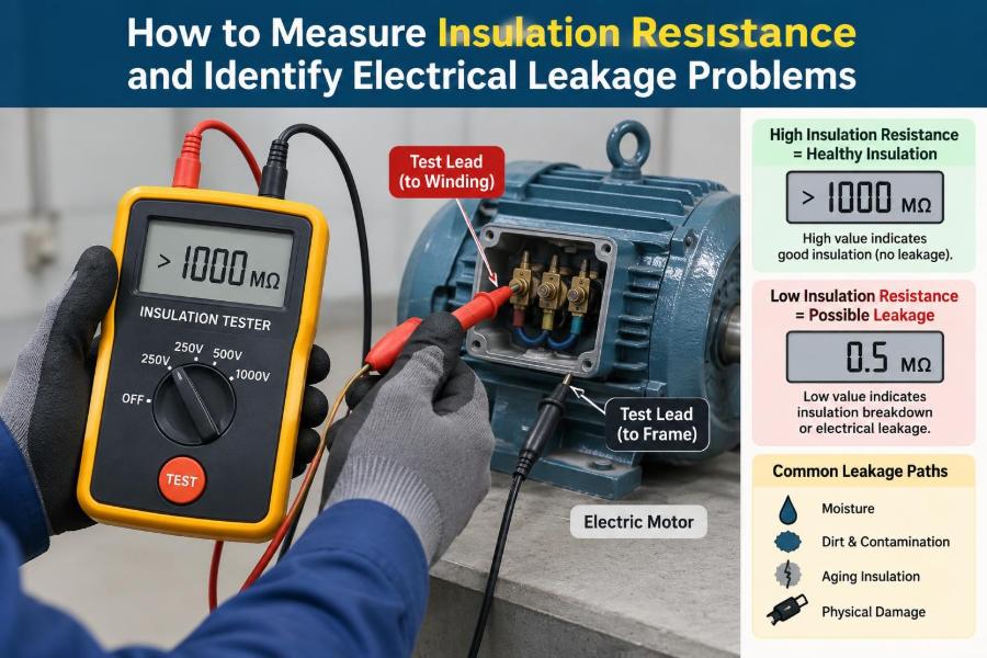
Insulation resistance is the opposition to current flowing through insulating material between conductors, or between a conductor and earth. It is normally expressed in megohms (MΩ), where one megohm equals one million ohms.
A high resistance means only a very small leakage current can pass at the test voltage. A low resistance means the insulation is allowing more current through than expected. The measurement is not a direct measure of insulation thickness; it is evidence of how clean, dry, intact, and electrically sound the insulation is at that moment.
🧱 Why conductors need an insulating barrier
Conductors are meant to carry current along a planned route. Their insulation keeps current from taking shortcuts to another core, a cable screen, a metal conduit, a machine frame, or earth.
Think of insulation as the wall of a water pipe. A small defect may not be visible from outside, but it can create a leak under pressure. An insulation tester applies a controlled DC voltage to reveal electrical “leaks” that ordinary continuity measurements may miss.
💧 What electrical leakage means in practice
Electrical leakage is unintended current flowing outside the intended circuit path. Some very small leakage is inherent in real insulation and in equipment containing filters or electronic power supplies. The concern is leakage that is excessive, unexpected, or able to energize accessible metalwork.
Leakage can flow from phase to earth, neutral to earth, between phases, or between winding sections. The route matters because it points toward the likely fault location and determines which protective device may operate.
🔍 Common causes of reduced insulation resistance
Insulation rarely fails without a mechanism. Finding that mechanism is more valuable than simply resetting protection or replacing a fuse.
- Moisture: condensation, flooded ducts, rain entry, and damp windings create conductive surface paths.
- Contamination: dust, oil, salt, chemicals, and conductive process residue can bridge insulation.
- Heat and ageing: thermal cycling can harden, crack, or degrade cable jackets and winding varnish.
- Mechanical damage: crushing, abrasion, tight bends, vibration, and poor cable pulling can expose or weaken insulation.
- Installation errors: trapped conductors, damaged glands, incorrect terminations, and mixed neutral connections can create leakage paths.
🧪 The basic principle of an insulation-resistance test
An insulation-resistance tester, often called a megohmmeter or “megger,” applies a specified DC test voltage and measures the resulting current. It then calculates resistance using Ohm’s law: R = V / I.
For example, a 500 V test producing 1 microampere of current corresponds to 500 MΩ. The tester displays the resistance directly, but the relationship is useful: at the same voltage, more leakage current means lower resistance.
📏 Resistance versus continuity testing
A multimeter continuity function is designed to find low-resistance paths such as wires, fuses, and bonded metalwork. It uses a low voltage and may show “open circuit” even when insulation has enough leakage to cause a nuisance trip at mains voltage.
An insulation tester uses a much higher DC voltage, commonly hundreds of volts. It tests the insulating barrier under a more demanding condition. These tools answer different questions, so one cannot substitute reliably for the other.
🛠️ Choose the right test instrument
Use an insulation-resistance tester with a suitable voltage range, a known calibration status, sound leads, and terminals rated for the work. Digital instruments often provide timed tests, automatic discharge, voltage indication, and data storage; analogue instruments can still be effective when properly maintained.
A clamp leakage meter is a complementary tool, not a replacement. It measures actual AC leakage current in an energized circuit by clamping around all live conductors together. It is useful for locating live-circuit leakage, while the insulation tester assesses isolated, de-energized circuits.
🔋 Select a test voltage that suits the equipment
The test voltage must suit the insulation system and the equipment connected to it. A higher voltage is not automatically a better test. Applying an unsuitable test to sensitive electronics, surge protection, controls, or variable-speed-drive components can damage them or produce misleading results.
| Typical application | Common test approach | Key caution |
|---|---|---|
| Extra-low-voltage/control circuits | Lower-voltage insulation test where appropriate | Disconnect electronic controls and sensors as required. |
| General low-voltage fixed wiring | Often tested at 500 V DC | Follow the applicable installation rules and equipment instructions. |
| Sensitive electronic equipment | Usually isolate before testing cable insulation | Do not apply a megohmmeter across connected electronics. |
| Motors and larger equipment | Voltage depends on rated voltage and manufacturer guidance | Consider winding condition, temperature, and test procedure. |
Always follow the relevant local electrical rules, the equipment manufacturer’s instructions, and your organization’s safe-work procedure. Test-voltage selection is a technical and safety decision, not a guess.
🛑 De-energize before connecting the tester
Insulation testing is normally a dead test. Isolate every possible supply, including alternate feeds, generators, UPS systems, photovoltaic sources, and control supplies. Apply lockout/tagout where the work environment requires it.
Then prove the circuit is dead with an approved voltage indicator and verify the indicator on a known source before and after use. Never assume an open switch has isolated every conductor; switching arrangements and borrowed supplies can leave parts energized.
⚠️ Understand stored-energy hazards
Capacitors, long cables, filter circuits, and electronic equipment can retain charge after isolation. An insulation tester also charges the item under test. The result may be a painful shock, an arc, or damage to connected components if the charge is not controlled.
Before and after testing, discharge according to the tester instructions and site procedure. Many modern testers discharge automatically, but that function should not replace verification. Keep hands away from exposed conductive parts while the test voltage is applied.
🧰 Inspect before you test
A visual inspection often identifies the fault faster than an instrument. Look for cracked jackets, discoloration at terminals, water trails, loose gland seals, pinched cables, oil-soaked insulation, rodent damage, and contamination around terminal blocks.
Record what you find before cleaning or dismantling anything. A damp cable entry, for example, can explain a low reading and guide corrective work. Testing is strongest when it supports physical evidence rather than replacing observation.
🔌 Disconnect loads that can distort or suffer from the test
Disconnect or isolate electronic drives, PLC inputs, power supplies, LED drivers, dimmers, surge protective devices, capacitors, instrumentation, and other manufacturer-designated equipment before applying an insulation test. Semiconductors may conduct at the test voltage or be harmed by it.
Also consider parallel paths. A reading taken across an entire board may include appliances, indicator lamps, contactor coils, and interconnected circuits. It may locate a problem broadly, but it will not reliably identify the individual faulty cable or device.
🗺️ Define exactly what is being tested
Write down the test boundaries before attaching leads: for example, “motor windings to frame,” “phase conductors tied together to protective earth,” or “core 1 to core 2 of cable C-14.” Clear boundaries make results repeatable and useful later.
For a three-phase cable, typical tests include each phase to earth and phase-to-phase combinations. For a motor, test each winding to frame and, where appropriate, between windings. The correct arrangement depends on the equipment and whether conductors have been separated.
🧭 A safe step-by-step test sequence
- Identify the circuit, its rating, connected equipment, and intended test voltage.
- Isolate all supplies, lock out where required, and prove dead.
- Disconnect sensitive equipment and separate conductors as needed.
- Inspect the cable, terminals, glands, and enclosure for obvious damage or moisture.
- Connect one lead to the conductor or conductors under test and the other to earth, frame, screen, or the second conductor.
- Keep clear of exposed metal, start the test, and observe the reading for the specified duration.
- Stop the test, allow the item to discharge, verify discharge, then remove leads.
- Record the result, test voltage, duration, temperature or conditions, and circuit configuration.
If any step is beyond your authorization or competence, stop and involve a qualified person. Insulation testing can create hazardous voltages even on a circuit that began de-energized.
⏱️ Why test duration changes the reading
Insulation is not a perfect resistor. When DC voltage is first applied, several currents occur: charging current, absorption current as insulating molecules polarize, and a smaller conduction current through the insulation.
In healthy, dry insulation, the displayed resistance often rises as the early currents decay. A reading that remains low or falls during a timed test can suggest moisture, contamination, or deterioration, although interpretation depends on the insulation type and equipment.
📈 Interpreting a rising, stable, or falling value
A single value is a useful screening result, but its trend during the test adds context. A steadily rising value is commonly consistent with dry, clean insulation. A low and stable value indicates a persistent leakage path. A falling value deserves investigation because current is increasing under sustained voltage.
Do not diagnose a machine solely from the shape of one curve. Temperature, surface contamination, winding construction, and the test setup all influence behavior. Compare like with like whenever possible.
🌡️ Temperature and humidity can mislead you
Warm insulation generally has lower resistance than the same insulation when cool, while humidity can sharply lower surface resistance. A motor tested in a humid plant after a washdown may read very differently from the same motor tested in a dry workshop.
Record ambient conditions and equipment temperature when results matter. Trend comparisons should be corrected or interpreted with temperature in mind; otherwise, a normal seasonal change may look like deterioration, or real deterioration may be overlooked.
📊 Use baseline data rather than chasing one “good” number
Minimum acceptance values can be specified by local rules, manufacturers, or maintenance procedures, but there is no universal pass number for every cable, motor, voltage class, and environment. A result can be above a general threshold yet still be concerning if it has fallen sharply from the equipment’s normal baseline.
Create records at commissioning and after known-good maintenance. Include the asset ID, circuit configuration, voltage, duration, temperature, humidity if known, and reading. Trending turns an isolated measurement into condition information.
🧮 Polarization index and dielectric absorption ratio
For some rotating machines and larger insulation systems, technicians use timed ratios. The polarization index compares insulation resistance at a later time, commonly ten minutes, with the one-minute value. The dielectric absorption ratio compares two shorter timed readings.
These ratios can help identify moisture or contamination because healthy insulation often continues to polarize. They are not suitable for every asset, especially modern low-capacitance systems or equipment with manufacturer-specific procedures. Use them only where the method is applicable and documented.
🏭 Testing motors and windings
For a disconnected motor, test winding-to-frame insulation with the frame bonded to the tester return lead. If winding ends are accessible and separated, test between windings as well. Ensure the motor is isolated from a variable-speed drive, starter electronics, and external control circuits first.
A low reading may arise from wet windings, dirt in the terminal box, damaged lead insulation, or internal winding degradation. Drying may improve a moisture-related result, but it is not proof that all damage has been removed; repeat testing and inspection remain necessary.
🏠 Testing cables and fixed wiring
For a cable, isolate both ends where possible. Test each core to protective earth or screen, then test core-to-core insulation. Separating conductors avoids parallel loads and makes the result more diagnostic.
In fixed installations, neutral-to-earth faults deserve special attention. Shared neutrals, connected appliances, and equipment filters can affect the reading. Divide the installation into smaller sections rather than repeatedly testing a whole building circuit and hoping the number reveals the location.
🧩 Divide and conquer to locate a leakage fault
When a large circuit gives poor insulation resistance, split it systematically at accessible junctions, distribution points, or disconnects. Test the supply side and each downstream branch separately. Keep a simple diagram and mark each result.
Suppose a warehouse lighting circuit tests poorly. Disconnecting branches may show that only the run serving a cold room is affected. Inspection can then focus on fittings, condensate exposure, cable entries, and connectors in that area instead of removing every luminaire.
🌧️ Moisture faults are often intermittent
Water-related leakage may appear only after rain, washdown, high humidity, or temperature changes that cause condensation. By the time testing occurs on a dry day, the resistance can recover enough to appear acceptable.
Match the investigation to operating conditions. Inspect enclosures after the event, look for failed seals and drainage paths, and compare readings when wet and dry if safe procedures permit. The real repair is often stopping water ingress, not merely drying the equipment.
🧼 Contamination and surface tracking
Dust alone is often harmless, but dust mixed with moisture, oil, salt, or conductive industrial residue can form a leakage path over insulation surfaces. Repeated leakage can carbonize material, creating tracking: a more permanent conductive route across the surface.
Cleaning must suit the material and site safety rules. Abrasive or inappropriate solvents can worsen damage. After cleaning and drying, inspect for carbon marks, cracks, and degraded clearances; a clean-looking surface is not necessarily a sound insulation system.
🔧 What to do after a low reading
Do not immediately energize a circuit simply because the reading improves slightly. First confirm the test arrangement, leads, voltage selection, and disconnected loads. Then inspect and isolate sections to distinguish a cable fault from a connected item.
- Remove moisture safely and address its entry route.
- Clean approved surfaces and replace contaminated or carbon-tracked components.
- Repair or replace mechanically damaged cable and failed glands.
- Dry windings only using an appropriate controlled method for the machine.
- Retest using the same documented configuration and compare results.
Where insulation damage is suspected inside sealed equipment, involve the manufacturer or a qualified repair facility rather than attempting improvised repairs.
🚫 Mistakes that produce false results
The most common error is testing with loads or electronics still connected. This can create a low reading through a legitimate component path, damage the equipment, or both. Another error is leaving parallel circuits joined, which hides the location of the problem.
Other avoidable mistakes include testing a live circuit, using contaminated test probes, forgetting to discharge, failing to record temperature, and comparing readings taken at different voltages or durations. A precise display does not make an uncontrolled test meaningful.
🧯 Do not confuse insulation testing with protective-device testing
A good insulation-resistance reading does not prove that an RCD, GFCI, breaker, fuse, earthing system, or protective bonding arrangement will operate correctly during a fault. Those functions require separate tests using appropriate instruments and procedures.
Conversely, a protective device that trips does not automatically prove insulation failure. Inrush current, overload, wiring errors, neutral-earth connections, and equipment with normal aggregate leakage can also be involved. Diagnose the trip mechanism before selecting a remedy.
🧑🔧 When to call a qualified professional
Seek competent assistance when testing involves distribution equipment, high-energy systems, medical or life-safety equipment, hazardous locations, high-voltage apparatus, complex drives, or circuits with uncertain feeds. The same applies when you find heat damage, repeated tripping, signs of arcing, or an energized metal enclosure.
Competence includes understanding the installation, the instrument, isolation methods, and applicable rules—not merely owning a tester. In many workplaces, insulation testing and returning equipment to service must be performed or verified by authorized personnel.
🗒️ Build a useful test record
A good record lets the next technician understand exactly what happened. Record the asset or circuit identification, date, tester ID, test voltage, duration, conductor configuration, result, environmental conditions, visual findings, and corrective action.
Also note what was disconnected. “500 V, phase conductors tied together to earth, motor drive disconnected, one-minute reading” is far more useful than “IR okay.” Clear documentation prevents invalid comparisons and supports planned maintenance.
🔁 Make insulation testing part of condition monitoring
Routine testing is most valuable when scheduled according to equipment criticality and environment. A clean, dry office circuit does not face the same exposure as a pump motor in a humid process area or a cable route exposed to vibration and weather.
Use results alongside thermography, visual inspections, leakage-current measurements, operating history, and protection-trip records. No single test describes the entire electrical condition, but combined evidence gives a stronger basis for maintenance decisions.
✅ The core principle: isolate, test, interpret, correct
Insulation resistance is not a score to collect; it is a clue about unintended current paths. A reliable process starts with safe isolation and correct test boundaries, uses a voltage appropriate to the insulation and connected equipment, and interprets results in their environmental and historical context.
The most effective troubleshooting sequence is simple: confirm the symptom, inspect, isolate sections, test methodically, identify the physical cause, correct it, and retest. That approach avoids both unnecessary replacement and the dangerous habit of treating a temporary improvement as a permanent repair.
Measure insulation resistance carefully, but use the result as part of a disciplined investigation into why electricity is escaping its intended path. Done well, the test protects people, preserves equipment, and turns an obscure fault into a solvable maintenance task. ⚡🛠️🔍