
A production line slows down for no obvious mechanical reason. An office UPS runs unusually warm. Lights flicker when a bank of chargers starts, and a transformer that appears correctly sized hums more loudly than expected.
These problems are often blamed on “dirty power,” a broad phrase that can hide a very specific electrical issue: harmonic distortion. Modern facilities contain more electronic loads than ever, and many of them draw current in short, uneven pulses rather than a smooth sinusoidal waveform.
That does not mean power electronics are inherently harmful. Variable-speed drives, efficient power supplies, battery chargers, LED drivers, and renewable-energy inverters deliver major advantages. But they must be designed and connected with attention to the quality of the power system around them.
Filters, converters, sound measurements, and careful system studies provide a practical path forward. The goal is not an ideal waveform in isolation; it is a reliable, efficient, and compatible electrical system.
⚡ What Harmonic Distortion Actually Means
In an ideal AC system, voltage and current follow a smooth sine wave at the fundamental frequency: typically 50 or 60 Hz. A harmonic is a sinusoidal component at an integer multiple of that fundamental frequency.
For a 60 Hz supply, the third harmonic is 180 Hz, the fifth is 300 Hz, and so on. When these components combine with the fundamental, the waveform becomes distorted.
Harmonics are not random electrical noise. They have identifiable frequencies, directions, and effects, which makes them measurable and, in many cases, manageable.
🌊 A Waveform Is Usually a Mixture, Not a Single Wave
A useful analogy is sound. A musical note can include a fundamental tone plus overtones that shape its character. Likewise, a distorted current waveform can be represented as a fundamental current plus harmonic currents.
This representation is central to power-quality analysis. It allows engineers to identify whether a problematic waveform is dominated by, for example, fifth- and seventh-order components or by higher-frequency switching components.
The source matters because a solution that works for low-order harmonics may have little effect on high-frequency emissions.
📏 Understanding THD Without Oversimplifying It
Total harmonic distortion, or THD, expresses the combined RMS value of harmonic components relative to the fundamental component. It is commonly reported as THD for voltage (THDV) or current (THDI).
A low current THD at one device does not automatically guarantee low voltage distortion at the point of connection. Voltage distortion depends on the harmonic current flowing through the system impedance, which includes transformers, cables, generators, and upstream network impedance.
THD is valuable, but it is not the whole diagnosis. The harmonic spectrum, loading level, measurement location, and time variation also matter.
🔌 Why Nonlinear Loads Create Harmonics
A linear load, such as an ideal resistance, draws current proportional to the applied voltage. A nonlinear load does not. Its current waveform may be clipped, pulsed, or delayed even when the supply voltage is nearly sinusoidal.
Many electronic devices use rectifiers and capacitors to convert AC into DC. The capacitor recharges near voltage peaks, so current is drawn in concentrated pulses rather than continuously across the full cycle.
Those pulses contain harmonic frequencies. The larger and more numerous the nonlinear loads, the greater the potential for system-level distortion.
🏭 Common Sources in Commercial and Industrial Systems
Harmonic-producing equipment is widespread. The most consequential sources are usually high-power loads or large populations of smaller electronic loads operating simultaneously.
- Variable-frequency drives and soft starters
- Uninterruptible power supplies and data-center power systems
- Rectifiers for electroplating, welding, traction, and DC processes
- LED lighting drivers and switched-mode power supplies
- Electric-vehicle charging equipment
- Solar photovoltaic and battery-storage inverters
- Arc furnaces and other rapidly changing industrial loads
Each technology has a different harmonic signature. Treating all nonlinear loads as identical leads to poor mitigation choices.
🔢 Why Certain Harmonic Orders Matter More
Three-phase six-pulse rectifiers commonly produce characteristic harmonics around orders expressed as 6k ± 1, such as the fifth, seventh, eleventh, and thirteenth. The exact spectrum changes with source impedance, DC-link conditions, switching strategy, and loading.
Lower-order harmonics are often especially significant because they can propagate efficiently through a facility and interact with power-factor correction equipment. Higher-order components may be more localized, but can still affect sensitive equipment and electromagnetic compatibility.
The correct question is not “which harmonic is always worst?” but “which frequencies are present here, at what magnitude, and where do they flow?”
🔺 Triplen Harmonics and the Neutral Conductor
In three-phase, four-wire systems, odd multiples of the third harmonic—third, ninth, fifteenth, and similar orders—are called triplen harmonics. Unlike balanced fundamental currents, these components are in phase in all three phases.
They add in the neutral rather than cancel. A heavily loaded neutral can therefore occur even when phase conductors appear reasonably balanced.
This is a common concern in buildings with many single-phase electronic loads. Neutral sizing, transformer selection, and measurement at the right point are all part of the response.
🔥 How Harmonics Turn Into Heat and Losses
Harmonic current raises RMS current, producing additional I²R losses in conductors. It can also increase transformer losses through eddy currents and stray flux effects, which tend to grow more significant at higher frequencies.
Motors can experience additional heating and torque pulsations when voltage harmonics are substantial. Capacitors may carry harmonic current beyond what their fundamental-frequency duty would suggest.
Heat is not merely an efficiency issue. Persistent excess temperature can reduce insulation life and erode the operating margin of electrical equipment.
🧰 Equipment Symptoms That Deserve Investigation
Harmonics are one possible explanation when equipment shows unexplained thermal stress or nuisance behavior. They should be investigated alongside loose connections, overloads, unbalance, poor grounding, control faults, and supply disturbances.
- Transformer or neutral conductor overheating
- Frequent capacitor fuse operation or capacitor-bank failures
- Unexpected breaker trips or relay misoperation
- Audible noise in transformers and motors
- Reduced generator capacity or unstable operation under nonlinear loading
- Erratic readings from instruments not designed for distorted waveforms
A symptom alone is not proof. Measurements and a one-line-system review are needed before assigning cause.
🏢 The Point of Common Coupling Changes the Perspective
The point of common coupling (PCC) is the point where a customer installation connects to the wider supply system or where multiple users share a portion of a network. It is a key location for assessing the effect of an installation on others.
A facility may have high current distortion internally while maintaining acceptable voltage distortion at its PCC if the system is sufficiently stiff. Conversely, a weak supply may develop noticeable voltage distortion from a comparatively modest nonlinear load.
This distinction helps separate internal equipment design from the broader responsibility of maintaining network compatibility.
📐 Why System Impedance Controls Voltage Distortion
At a given harmonic frequency, harmonic current flowing through impedance creates a harmonic voltage drop. In simplified form, the relationship follows Vh = IhZh.
Long cable runs, lightly loaded generators, smaller transformers, and network configurations can make the effective impedance more influential. Impedance also changes with frequency, so a system cannot be judged from its fundamental-frequency impedance alone.
This is why a drive that behaves well on a robust utility feeder may cause more visible distortion when the same load is supplied by a standby generator.
🧪 Measuring Before Selecting a Remedy
A power-quality survey should capture voltage and current waveforms, harmonic spectra, demand, power factor, unbalance, and operating states over a representative period. A short measurement during a quiet shift can miss the condition that actually causes the problem.
Portable analyzers should be installed safely and configured with appropriate voltage and current ratios. Their sampling capability and reporting method must suit the frequency range being investigated.
Useful measurements are tied to events: which drives were running, whether capacitor stages were energized, what the generator was doing, and how load changed over time.
🗺️ Start With a One-Line Diagram and Load Inventory
Measurements become far more useful when mapped onto an accurate single-line diagram. Record transformer ratings and impedances, feeder sizes, capacitor banks, generators, drives, UPS units, and major nonlinear loads.
Also identify locations of sensitive loads. A laboratory instrument, communication system, or precision process may need a different mitigation approach than a robust motor load.
For new installations, a harmonic study should happen before equipment is purchased or connected—not after a capacitor bank starts failing.
📚 Standards Guide the Conversation, Not the Diagnosis Alone
Engineering practice often uses standards and utility requirements to set planning limits and evaluate compatibility. Documents such as IEEE 519 are widely referenced for harmonic control at the PCC, while equipment standards address particular device categories.
Limits depend on system conditions and the ratio of available fault current to maximum demand current. They are not universal pass/fail values that can be copied from one project to another.
A compliant value at one measurement point also does not prove that every internal device is protected from harmonic heating or resonance.
🧱 Passive Filters: Simple Components, Careful Design
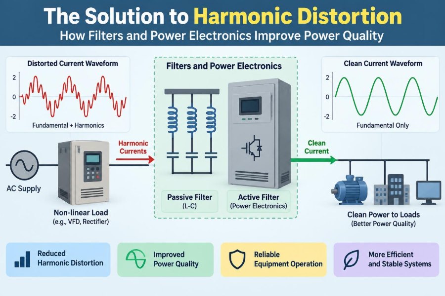
Passive harmonic filters use inductors, capacitors, and sometimes resistors. They create low-impedance paths for selected harmonic frequencies or alter the system’s frequency response so problematic current is diverted away from the supply.
A single-tuned filter is designed around one target frequency. High-pass and damped arrangements can address a broader range, particularly at higher frequencies.
Passive filters can be efficient and economical for stable, predictable loads. Their performance, however, depends strongly on the surrounding electrical system.
🎯 Tuned Filters Need Detuning and Tolerance Checks
Component tolerances, temperature, capacitor aging, and changing network impedance shift the actual tuning frequency. A filter designed too sharply can miss its intended target or interact unfavorably with another part of the system.
Engineers therefore consider detuning, quality factor, expected loading, switching transients, and contingencies such as an out-of-service capacitor stage. The filter must also be rated for its actual harmonic current and voltage stress.
A tuned filter is not simply “a capacitor bank with an inductor.” Its protection, thermal design, and system interaction require analysis.
⚠️ Resonance Is the Passive-Filter Risk to Respect
Capacitors and inductive network elements can form resonant circuits. At resonance, the network can amplify harmonic voltage or current rather than reduce it.
Parallel resonance is a frequent concern when conventional power-factor correction capacitors are added to a system containing nonlinear loads. A harmless-looking capacitor addition can move the resonant frequency close to a dominant harmonic.
Detuned capacitor banks use series reactors to shift this response away from troublesome frequencies. This is often a better starting point than adding plain capacitors to a distorted system.
🧠 Active Harmonic Filters Adapt to Changing Loads
An active harmonic filter measures load current and injects compensating current with opposite harmonic content. In effect, it cancels selected distortion components at its connection point.
Because it is controlled electronically, an active filter can respond to varying load patterns and may also compensate reactive power or phase unbalance within its ratings. This flexibility is valuable in facilities where load composition changes throughout the day.
Its limits still matter: the device has a finite current capacity, a defined bandwidth, losses, control requirements, and an installation location that determines what it can actually correct.
🔀 Hybrid Filters Combine Two Strengths
Hybrid solutions pair passive components with active compensation. The passive portion handles a large, predictable share of harmonic current, while the active portion manages variation or remaining components.
This arrangement can reduce the active filter’s required rating in high-power applications. It can also improve performance where a passive-only design would be too narrow and an active-only design would be unnecessarily large.
As with all combined systems, coordination is essential. Controllers and passive branches should be studied as a single network, not selected independently.
🔄 Line Reactors and DC Chokes Reduce Harmonics at the Source
For many drives and rectifiers, a line reactor or DC-link choke is a practical first measure. Added inductance smooths current pulses, limits inrush, and reduces some harmonic content.
These components do not provide the broad, precise cancellation of an active filter, but they are robust and often improve the behavior of individual equipment at modest complexity.
Input reactors must be sized for voltage drop, current, thermal duty, and the drive manufacturer’s recommendations. Excessive impedance can affect available voltage and drive operation.
🌐 Multi-Pulse and Phase-Shifting Rectifier Arrangements
Multi-pulse rectifier systems use phase-shifting transformers and multiple rectifier bridges to cancel selected characteristic harmonics on the supply side. Twelve-pulse arrangements, for example, can reduce some harmonics associated with a six-pulse front end.
They are often effective in large, steady industrial installations. Their drawbacks include transformer complexity, physical size, cost, and reduced benefit when load balance between bridges is poor.
They remain a useful option when a facility values ruggedness and has a suitable transformer architecture.
🧭 Active Front Ends Change the Current Waveform
An active front end (AFE) uses controlled semiconductor switches rather than a simple diode rectifier at the input of a drive or converter. Properly designed controls can shape input current to be close to sinusoidal and operate with controllable displacement power factor.
AFEs can reduce low-order harmonics and support regenerative operation, allowing energy from a decelerating load to flow back to the supply or a common DC bus where permitted.
They introduce switching-frequency components and require attention to electromagnetic interference, filtering, control stability, and installation practice. “Low harmonic” does not mean “no engineering required.”
🔋 Inverters Can Support Power Quality Too
Grid-connected inverters are often discussed as harmonic sources, but their fast control can also support voltage regulation, reactive-power control, and harmonic mitigation in some architectures. Whether they provide these functions depends on hardware capability, controls, grid-code permissions, and coordination with protection systems.
Inverter-based resources should not be assumed to solve a facility harmonic problem automatically. Their available current headroom may be limited during high real-power output, and their control objectives may prioritize other functions.
Still, power electronics increasingly allow power quality to be managed dynamically rather than only with fixed passive components.
⚙️ Displacement Power Factor Is Not True Power Factor
Displacement power factor describes the phase relationship between fundamental voltage and current. True power factor also reflects waveform distortion.
A nonlinear load may have near-unity displacement power factor while still drawing distorted current and having a lower true power factor. Adding capacitors may improve displacement power factor without solving harmonic distortion.
This distinction prevents a common mistake: selecting a power-factor correction solution from a single meter reading without reviewing waveform quality.
🚫 Common Mitigation Mistakes
Several shortcuts repeatedly create new problems or leave the original one unresolved.
- Adding capacitors first: this can create resonance if the harmonic environment is unknown.
- Sizing from total kW alone: harmonic current, source stiffness, load diversity, and future expansion affect the answer.
- Filtering at the wrong location: a branch filter may not protect upstream equipment, while a central filter may not solve a sensitive local issue.
- Ignoring generator operation: a mitigation design that works on utility power may perform differently on a generator.
- Trusting one snapshot: intermittent loads require time-based measurement.
The recurring lesson is straightforward: characterize the system before changing its impedance.
🛠️ A Practical Harmonic-Mitigation Workflow
- Define the concern: compliance, overheating, nuisance trips, voltage distortion, or sensitive-load performance.
- Gather the single-line diagram, equipment data, operating schedules, and expansion plans.
- Measure voltage and current at relevant buses and feeders during representative conditions.
- Identify dominant frequencies, current paths, and potential resonance points.
- Model or calculate candidate solutions, including normal and contingency operating states.
- Select equipment with verified ratings, protection, and coordination.
- Commission with post-installation measurements and retain a baseline for future comparison.
For complex facilities, this work should be performed or reviewed by qualified power-system engineers. Site conditions can overturn assumptions made from nameplate data alone.
🏥 Application Priorities Differ by Facility
A data center may prioritize UPS compatibility, neutral loading, generator operation, and continuity during switching events. A manufacturing plant may focus on drive harmonics, capacitor-bank reliability, and process uptime.
In a hospital or laboratory, sensitive equipment and continuity of care can justify stricter internal power-quality goals than the minimum network requirement. In a renewable-energy plant, inverter interactions and collection-system resonance may be central concerns.
The best solution is therefore application-specific. Equipment type matters, but the electrical context matters just as much.
🧯 Protection, Maintenance, and Safety Still Apply
Filters and power-electronic equipment carry stored energy and may operate at substantial current. Isolation, discharge arrangements, fusing, ventilation, grounding, arc-flash procedures, and maintenance access must be part of the design.
Capacitor capacitance can decline with age, reactors can overheat, and connections can loosen under thermal cycling. Periodic inspection and trend measurements help reveal deterioration before a failure changes the system response.
Only qualified personnel should install, test, or modify energized power equipment. Harmonic mitigation is an electrical-system change, not a plug-in accessory.
📈 Design for Expansion, Not Only Today’s Load
New chargers, automation equipment, servers, drives, and inverter-based resources can change both harmonic levels and resonant frequencies. A solution with no capacity margin may become inadequate after an otherwise routine upgrade.
Document baseline spectra, filter settings, capacitor stages, and assumed load cases. Future engineers can then distinguish a genuine new issue from a pre-existing condition.
Planning for expansion does not always mean buying the largest filter now. It means leaving physical, electrical, and analytical room for a deliberate upgrade.
🔍 The Core Principle: Match the Solution to the System
Harmonic distortion is not solved by a single component chosen from a catalog. It is controlled by understanding the source of harmonic current, the impedance of the network, the loads that are vulnerable, and the operating conditions that matter.
Passive filters, active filters, reactors, multi-pulse systems, and active-front-end converters all have valid roles. Their value depends on frequency range, load variability, system strength, maintenance capability, cost, and interactions with capacitors and generators.
Measure the waveform, model the network, and apply mitigation where it addresses the actual mechanism—not merely the visible symptom.
Clean power quality comes from coordinated design: nonlinear loads, filters, converters, conductors, transformers, and protection must be treated as one electrical system. With that perspective, harmonic control becomes a practical engineering discipline rather than a cycle of trial-and-error fixes. ⚡🔧📊