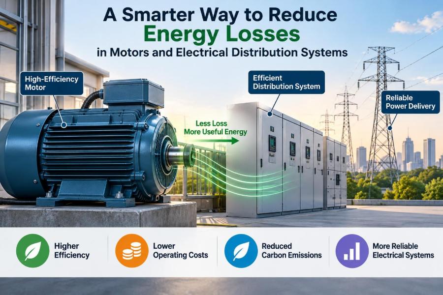

A production line slows down, a pump runs warmer than expected, or a building’s electricity bill climbs even though operating hours have barely changed. These events are often treated as separate maintenance or budgeting problems. In many cases, they share a common cause: energy is being lost somewhere between the supply and the useful work.
Electrical losses are not mysterious. Conductors heat up, transformers have internal losses, motors consume reactive power, and poor connections create resistance exactly where it is least welcome. The challenge is that each loss may appear small when viewed alone.
Across a facility, those small losses can combine with poor power quality, unsuitable equipment sizing, and operating habits. The result is higher energy use, reduced equipment life, avoidable downtime, and less capacity for useful loads.
A smarter approach does not begin by replacing every motor or installing every available efficiency device. It begins by measuring the system, understanding where energy is going, and selecting improvements that fit the actual load, network, and operating pattern.
🔍 Energy Loss Is More Than a Higher Utility Bill
Energy loss is electrical input that does not become the intended output. In a motor-driven pump, the intended output may be water flow and pressure. In a distribution system, it may be reliable electrical power delivered to a load at the required voltage.
Some losses are unavoidable because real materials have resistance and real machines require magnetizing current. The goal is not a physically impossible zero-loss system. The goal is to identify unnecessary or excessive loss and reduce it without compromising safety, reliability, or process performance.
Losses also create heat. That heat can raise conductor, insulation, bearing, winding, and panel temperatures, accelerating ageing even when a component has not yet reached its rated limit.
⚙️ Follow the Energy Path Before Choosing a Fix
Think of the installation as an energy path: utility or generator, main switchboard, transformer, feeders, motor control equipment, motor, driven machine, and process. At every stage, electrical energy can be converted into unwanted heat, magnetic loss, vibration, noise, or harmonic currents.
This path matters because the visible symptom is not always at the source. A hot motor may be reacting to voltage imbalance upstream. A high feeder current may be caused by poor power factor or harmonics created by downstream loads.
Tracing energy from source to use prevents the common mistake of treating the motor and the distribution network as unrelated systems.
🔥 The Basic Physics: Why Current Creates Heat
The familiar conductor-loss relationship is P = I²R, where P is power loss, I is current, and R is resistance. This is commonly called I²R loss, copper loss, or resistive loss.
The squared-current term is especially important. If current rises, heat loss rises much faster. That is why reducing needless current through correct conductor sizing, better power factor, load balancing, or voltage optimization can have a meaningful effect on feeder heating.
Resistance also increases as metallic conductors become hotter. A heavily loaded cable can therefore enter an unfavorable cycle: more current causes more heat, and more heat raises resistance, which produces still more loss.
📏 Voltage Drop Is Both a Loss and a Performance Clue
Voltage drop is the reduction in voltage along a conductor caused by its impedance, which includes resistance and alternating-current effects such as reactance. A modest voltage drop may be acceptable; excessive drop can impair equipment operation.
Motors are sensitive because torque capability depends strongly on applied voltage. If voltage at the motor terminals falls under load, a motor may draw more current to meet the mechanical demand, producing additional heating.
Voltage drop should be assessed during real operating conditions, not only when equipment is idle. A measurement at the main board may look healthy while a distant motor terminal sees a poorer supply.
🧵 Conductor Size and Route Set the Distribution Baseline
Undersized conductors have higher resistance and therefore greater losses at a given current. Yet choosing the largest available conductor is not automatically the best design; cost, installation method, fault protection, termination capacity, and expected load all matter.
Route conditions are equally important. Long runs, high ambient temperature, cables grouped in trays, poor ventilation, and conductors installed near heat sources can all limit thermal performance and increase resistance.
A sound design checks ampacity, voltage drop, short-circuit duty, derating factors, and the realistic future load. For existing systems, thermal inspection and loaded voltage measurements can reveal where the original assumptions no longer match reality.
🔩 Loose Connections Behave Like Tiny Heaters
A loose, corroded, damaged, or poorly crimped connection can have much more resistance than the conductor around it. The resulting localized I²R heating may remain hidden inside a panel, junction box, terminal compartment, or cable lug.
Heat can worsen the problem by oxidizing contact surfaces, weakening spring pressure, and damaging insulation. This is not simply an efficiency issue; it can become a reliability and fire-risk concern.
Useful maintenance includes torque procedures based on equipment instructions, clean compatible contact surfaces, correct lugs and tooling, and inspection after conditions that can loosen hardware, such as vibration or thermal cycling.
🌀 Understand Where an Induction Motor Loses Energy
Induction motors remain common because they are rugged and practical, but their efficiency is never perfect. Input electrical power is divided among useful shaft output and several loss mechanisms.
| Loss category | Where it occurs | What often influences it |
|---|---|---|
| Stator copper loss | Stator windings | Current, winding resistance, temperature |
| Rotor copper loss | Rotor conductors | Load and slip |
| Core loss | Magnetic steel | Voltage, frequency, magnetic flux |
| Mechanical loss | Bearings, fan, air movement | Speed, lubrication, alignment |
| Stray-load loss | Various electromagnetic effects | Design, waveform quality, loading |
The practical lesson is that motor losses do not all respond to the same intervention. Reducing mechanical drag will not correct voltage imbalance, and a more efficient motor cannot compensate for a badly throttled pump system.
📊 Efficiency Is a Ratio, Not a Nameplate Promise
Motor efficiency is the ratio of shaft output power to electrical input power. It varies with loading, supply conditions, temperature, and motor design. A nameplate efficiency is useful, but it describes performance under specified conditions rather than every operating point.
Efficiency generally falls at very low load because fixed losses, such as core and friction losses, become a larger share of the input. That does not mean every lightly loaded motor must be replaced. Starting duty, torque requirements, process variability, and the cost of change need to be considered.
Measure the operating load where possible. Current alone is an imperfect proxy for shaft load, especially when power factor is low or waveform distortion is present.
🏋️ Right-Size Motors for the Actual Duty
An oversized motor may operate far below its efficient region and can cost more to purchase and control. An undersized motor may run hot, struggle during starts, and have a shortened service life.
Right-sizing starts with the driven load. Pumps and fans have different torque-speed behavior from conveyors, crushers, compressors, and hoists. A motor selected only from a rough estimate may be mismatched before installation begins.
- Review normal and peak torque requirements.
- Consider starting method and acceleration time.
- Check whether the load is continuous, intermittent, or cyclic.
- Allow for realistic future capacity, not unlimited speculation.
- Verify service conditions such as altitude, ambient temperature, and enclosure ventilation.
A motor with adequate starting torque and a sensible operating load is usually a better choice than one selected solely for maximum nameplate power.
🏭 Efficient Motors Help Most in Long-Running Applications
High-efficiency motors reduce internal losses through design improvements such as lower-resistance windings, improved magnetic materials, and optimized air gaps. Their value is greatest when they operate for many hours at meaningful load.
However, replacement decisions should include the whole application. If a motor runs only occasionally, or if the driven equipment wastes much more energy than the motor itself, a motor upgrade may not be the first priority.
For a failed motor, the decision between rewinding and replacement deserves care. A quality repair can preserve performance, while a poor rewind can alter winding characteristics or damage core laminations. Evaluate the motor’s condition, criticality, repair quality, and operating hours rather than applying a single rule.
🌡️ Temperature Is an Early Warning Signal
Heat is often the visible evidence of hidden loss. A motor operating unusually hot may have overloaded windings, restricted cooling, poor supply quality, bearing friction, frequent starts, or a mismatch between motor and load.
Temperature comparisons are most useful when they compare similar components under similar load and ambient conditions. A thermal image can identify a suspicious phase connection or breaker terminal, but it does not by itself identify the root cause.
Trend data is more informative than a single reading. If the temperature of one connection rises over successive inspections at similar current, investigate before damage becomes severe.
⚖️ Three-Phase Voltage Imbalance Can Multiply Motor Stress
In a three-phase system, the phase voltages should be close in magnitude and properly separated in phase angle. Voltage imbalance can arise from uneven single-phase loads, poor connections, transformer issues, or supply-side conditions.
Even a relatively small voltage imbalance can produce disproportionately larger current imbalance in a motor. That uneven current raises winding temperature and can reduce available torque.
Measure all phase-to-phase voltages at the motor terminals while it is operating. If imbalance is found, examine the upstream system and phase loading rather than assuming the motor is defective.
🧲 Power Factor Explains Why Current Can Be Higher Than Expected
Alternating-current systems supply both real power and reactive power. Real power performs useful work, while reactive power supports magnetic fields in equipment such as induction motors and transformers. The combination is apparent power.
Power factor describes how effectively apparent power is being converted to real power. A lower power factor means more current is needed to deliver the same real power at a given voltage. That added current increases conductor losses and consumes capacity in transformers, switchgear, and feeders.
Low power factor is not identical to low efficiency. A motor can be reasonably efficient but still draw substantial magnetizing current, particularly when lightly loaded.
🔌 Use Power-Factor Correction Carefully
Capacitors can supply reactive power locally, reducing the reactive current drawn from upstream equipment. This can lower feeder current and release system capacity where the power factor is genuinely poor.
Placement matters. Fixed capacitors may suit steady loads, while switched banks may better follow changing demand. Capacitors installed at a motor need suitable switching and protection arrangements so they do not create operating problems during starting or disconnection.
Do not add capacitors without checking harmonic conditions. Capacitors can interact with system inductance and amplify certain harmonic currents. Where nonlinear loads are significant, an engineering assessment may call for detuned reactors, filtering, or a different strategy.
🌊 Harmonics Add a Different Kind of Electrical Burden
Harmonics are voltage or current components at frequencies that are multiples of the fundamental supply frequency. They are commonly associated with nonlinear loads, including some electronic drives, rectifiers, uninterruptible power supplies, and switched-mode power supplies.
Harmonic currents can increase heating in transformers, neutral conductors, cables, and motors. They can also distort voltage, interfere with sensitive equipment, and complicate measurements made with instruments not designed for non-sinusoidal waveforms.
The appropriate response depends on measurement, not guesswork. A power-quality assessment can identify the waveform, the operating conditions, and whether a particular load is materially contributing to the issue.
🎛️ Variable-Speed Drives Can Avoid Waste at the Source
Variable-speed drives, often called VFDs or VSDs, control motor speed by changing the supplied frequency and voltage. They are especially valuable when a process frequently requires less than full flow, pressure, or air movement.
For centrifugal pumps and fans, reducing speed can reduce power demand substantially because their behavior follows affinity relationships. In contrast, using a damper, bypass, or throttling valve often keeps the motor near full speed while deliberately adding resistance to the process.
A drive is not a universal energy-saving device. If a conveyor must run at one constant speed or a compressor has a fixed optimal operating point, the savings may be limited. The load profile decides the opportunity.
🛠️ Drives Need Installation Discipline
A VFD changes the electrical environment of the motor. Fast voltage transitions can stress motor insulation, long motor cables can create reflected-wave effects, and common-mode currents can contribute to bearing damage in some installations.
Good practice may include appropriately rated motors, suitable cable, correct grounding and bonding, line or output reactors where needed, and attention to cable length. The correct arrangement depends on the drive, motor, system voltage, and manufacturer guidance.
Drives also produce harmonics on their input side. Their energy benefit should therefore be considered alongside power-quality effects, not treated as an isolated motor decision.
💨 Mechanical Loss Often Starts in the Driven Equipment
A motor does not know whether its shaft power is producing useful output or overcoming unnecessary resistance. Misalignment, worn bearings, belt tension errors, clogged filters, blocked ducts, poor lubrication, and rubbing components all increase mechanical demand.
Consider a hypothetical fan that must move air through a dirty filter. The motor may be electrically healthy, but the system requires more pressure to maintain flow. Cleaning the filter can reduce the required shaft power without changing the electrical equipment.
This is why energy reviews should include mechanics and process engineering. Electrical measurements identify symptoms; the driven system often reveals the cause.
💧 Pump Systems Reward System-Level Thinking
Pumping losses frequently arise from oversizing, excessive pipe friction, unnecessary throttling, leaks, recirculation, and operation far from the pump’s preferred region. A more efficient motor helps, but it may be a smaller opportunity than correcting the hydraulic system.
Start with the required flow and head, then compare them with actual operating conditions. Pressure gauges, flow measurements, valve positions, and pump curves can reveal whether energy is being used to overcome avoidable restrictions.
Where demand changes over time, speed control may be useful. Where demand is stable, improving pipework, impeller selection, or pump sizing may provide a simpler long-term answer.
🏢 Transformers Have No-Load and Load-Dependent Losses
Transformers consume energy even when they are lightly loaded. Core loss is largely associated with energization, while winding loss increases with load current. The relative importance of each depends on the transformer’s duty cycle.
A transformer left energized continuously with little load may make no-load loss a meaningful consideration. A heavily loaded transformer may be dominated by winding loss and temperature rise. Neither condition is automatically wrong, but both should be evaluated against actual use.
Improving transformer efficiency may involve selecting an appropriate rating, avoiding unnecessary parallel operation of lightly loaded units, maintaining cooling systems, and checking for abnormal heating or poor connections.
⚡ Balance Loads to Use Three-Phase Capacity Better
Uneven distribution of single-phase loads across a three-phase system can create voltage imbalance, neutral current, and unequal heating. It also leaves some phase conductors more heavily loaded than others.
Load balancing is a practical review of which circuits are connected to each phase and when they operate. The best arrangement is based on measured demand over time, not merely the number of circuits per phase.
Rebalancing should be planned and performed by qualified personnel with proper isolation and verification procedures. Moving a circuit without understanding its supply arrangement can create safety or operational problems.
🧪 Measure Real Power, Not Just Amps
A clamp meter is valuable, but current alone cannot fully explain energy use. For three-phase loads, useful measurements can include voltage, current, real power in kilowatts, apparent power in kilovolt-amperes, power factor, demand trend, and harmonic distortion.
A portable power analyzer used over a representative operating period can reveal cycling loads, low-load running, peak-demand events, phase imbalance, and changes between production modes. That evidence is far stronger than a snapshot taken during a convenient moment.
Instrumentation must be suitable for the system and installed safely. Electrical testing around energized equipment should follow site procedures and be performed by competent people using appropriate protective measures.
📈 Establish an Energy Baseline Before Claiming Savings
An energy baseline describes normal consumption and operating conditions before a change. It might include kilowatt-hours, run time, throughput, flow, ambient conditions, pressure, or product volume, depending on the process.
Without a baseline, a lower electricity bill might be attributed to an upgrade when production simply declined or weather changed. Likewise, an improvement can be missed if output increased at the same time.
Use a fair comparison: similar operating periods, known production conditions, and clearly documented changes. Savings estimates should state their assumptions instead of implying certainty where operating conditions vary.
🧭 Prioritize Projects by Loss Mechanism and Operating Hours
The best project is not necessarily the one with the newest technology. It is often the one that addresses a large, persistent loss with a practical implementation path.
- Fix overheated or degraded connections promptly for safety and reliability.
- Address continuously running, poorly controlled pumps and fans early.
- Correct chronic voltage imbalance and overloaded feeders.
- Improve power factor where measurements show excess reactive current and harmonic risk has been assessed.
- Plan motor upgrades around replacement cycles when an immediate retrofit is not justified.
Rank opportunities using measured energy impact, runtime, maintenance benefit, process risk, capital cost, and expected service life. This makes the plan defensible and prevents attention from being diverted to small, highly visible changes.
🧰 Preventive Maintenance Is an Efficiency Strategy
Maintenance is sometimes separated from energy management, but the two are tightly linked. Dirty cooling passages, poor lubrication, worn belts, loose terminals, and unbalanced loads all force equipment to operate less efficiently.
A useful routine combines electrical and mechanical checks: inspect connections, clean ventilation paths, assess vibration and alignment, review temperature trends, check voltage balance, and record abnormal current or power-factor readings.
Condition-based maintenance is especially effective when it uses trends. A change from normal behavior is often more meaningful than a single absolute value without context.
🚫 Avoid Common “Quick Fix” Mistakes
Several popular actions can create disappointment because they treat a symptom rather than the system. Adding capacitors without harmonic review, installing a VFD on an unsuitable process, or replacing motors based only on age can waste money or introduce new problems.
Another mistake is using nameplate data as operating data. A motor’s rated current, rated power, and catalog efficiency are necessary reference points, but they do not tell you what the machine is doing at this moment.
Finally, do not confuse reduced current with reduced energy in every situation. A change in power factor can lower current and distribution losses while leaving the real process energy nearly unchanged. Both outcomes can be valuable, but they should be described accurately.
🧑🔧 Safety and Coordination Come Before Optimization
Electrical efficiency work often involves live measurement, equipment settings, conductor modifications, and control changes. These activities carry shock, arc-flash, rotating-equipment, and process hazards.
Follow applicable local codes, site safety rules, lockout and verification procedures, and manufacturer instructions. Protective-device coordination must not be compromised merely to reduce nuisance tripping or accommodate a new load.
Where the issue involves protection, harmonic resonance, drive installation, transformer loading, or supply quality, involve qualified electrical engineers and technicians. A technically sound energy improvement must also remain safe under normal operation and fault conditions.
🗺️ Build a Practical Improvement Roadmap
Start with an asset list: major motors, transformers, feeders, operating hours, process roles, known faults, and available metering. Then identify a short list of loads that are large, continuous, hot, unreliable, or visibly controlled by wasteful methods.
- Gather representative electrical and process measurements.
- Identify the loss mechanism rather than assuming the remedy.
- Correct urgent safety and reliability defects first.
- Compare operational, mechanical, electrical, and control solutions.
- Implement a change with documented settings and baseline data.
- Verify performance and keep monitoring the result.
This sequence turns energy reduction from a collection of purchases into a repeatable engineering practice.
🎯 The Core Principle: Reduce Unnecessary Current and Unnecessary Work
The most effective improvements usually reduce one of two things: unnecessary electrical current in the distribution system or unnecessary mechanical work in the process. Often, a good project reduces both.
Correcting a poor connection lowers resistive heating. Balancing phases improves supply conditions. Improving power factor can reduce upstream current. Variable speed can eliminate throttling losses. Repairing a mechanical problem reduces the torque the motor must produce.
These measures work best when chosen from evidence. Measure the real operating system, locate the dominant loss, and correct the cause rather than purchasing a generic “efficiency” solution.
Smarter energy use comes from treating motors, controls, mechanical loads, and distribution equipment as one connected system—not as separate boxes on a diagram. That approach lowers waste while supporting the reliability and safety that electrical systems are meant to deliver. ⚡🔧📉