
A pump starts sluggishly at the far end of a building. A run of garden lights looks dimmer near the last fitting. A workshop compressor trips even though its circuit breaker appears correctly rated. In each case, the load may be perfectly healthy; the supply conductors may be the real problem.
Every cable has resistance. When current travels through it, some voltage is lost along the route and some electrical energy becomes heat. On a short domestic branch circuit this loss is often modest. On a long feeder, a low-voltage system, or a circuit carrying high current, it can determine whether equipment works reliably at all.
Cable sizing is therefore not simply a matter of picking a conductor that will survive the expected current. A sound design must also deliver adequate voltage at the load, coordinate with protective devices, withstand installation conditions, and meet the rules that apply where the work is done.
Voltage-drop calculations turn that design problem into a sequence of manageable decisions. The formulas are straightforward, but the assumptions behind them deserve careful attention.
⚡ What Voltage Drop Actually Means
Voltage drop is the reduction in electrical potential between the source and the load caused by impedance in the conductors. A cable is not an ideal wire: it has resistance, and in AC circuits it may also have reactance.
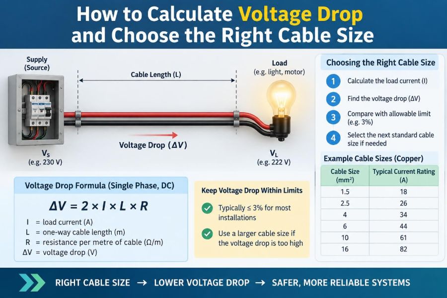
If a source supplies 230 V and a load receives 224 V while operating, the circuit voltage drop is 6 V. That 6 V is not “used up” by the load; it is lost in the wiring before the load terminals.
🔌 Why Loads Care About the Delivered Voltage
Equipment is designed to operate within a stated voltage range. A modest drop may have little noticeable effect on a resistive heater, but motors, electronic power supplies, contactors, and LED drivers can respond very differently.
- Induction motors may draw higher current, develop less starting torque, and run hotter when undervoltage is significant.
- Electronic equipment may shut down, reset, or report supply faults if its input range is exceeded.
- Low-voltage lamps can dim visibly because a few volts represent a large percentage of their nominal supply.
- Control circuits can suffer relay chatter or failure to pull in.
The question is not only whether the cable is safe. It is whether the connected equipment receives a suitable supply during normal operation and, where relevant, during starting or fault conditions.
🧭 Separate Voltage Drop From Current Capacity
Two checks are commonly confused. Ampacity, often called current-carrying capacity, asks whether the conductor insulation and installation can safely carry the current without excessive temperature rise. Voltage drop asks whether the conductor is electrically large enough and short enough to deliver the required voltage.
A cable can pass one check and fail the other. For example, a conductor may safely carry 10 A when installed in open air, yet create excessive voltage drop over a long run. Conversely, a large conductor may have very low voltage drop but require derating if bundled in thermal insulation or grouped with other loaded cables.
📏 The Basic Resistance Formula
For a DC circuit, or an AC circuit where reactance is negligible, cable resistance is approximated by:
R = ρL / AHere, R is resistance in ohms, ρ is the conductor material resistivity, L is conductor length, and A is conductor cross-sectional area. The relationship explains the design levers: longer cables have more resistance, while a larger cross-sectional area has less.
Copper is widely used because it has low resistance and good connection properties. Aluminium is lighter and often economical for larger feeders, but it has higher resistance for the same area and needs correctly rated terminations and installation practices.
🔁 Why Circuit Length Is Usually Twice the Route
Current must travel out to the load and return to the source. In a two-wire single-phase or DC circuit, both conductors contribute to the voltage loss.
If a load is 40 m from the supply, the usual resistive calculation uses a loop length of 80 m. Forgetting the return path is one of the most common calculation errors and can make a result look half as severe as it really is.
Three-phase calculations use a different expression because the phase conductors share the return path through the balanced system. Do not automatically double the one-way length in a balanced three-phase formula.
🧮 The Simple DC and Single-Phase Formula
For a simple resistive approximation, calculate voltage drop with:
Vdrop = I × RloopUsing the resistance expression, this becomes:
Vdrop = I × (2ρL / A)I is load current, and L is the one-way route length. This form is useful for battery systems, DC lighting, and preliminary single-phase cable estimates, provided the resistance value corresponds to the cable’s operating condition.
📐 A Worked Single-Phase Example
Consider a hypothetical 230 V single-phase load drawing 16 A, located 30 m from its distribution board. Suppose the selected cable has a tabulated conductor resistance of 7.4 milliohms per metre at the relevant temperature.
The loop length is 60 m. The loop resistance is 0.0074 Ω/m × 60 m = 0.444 Ω. The estimated drop is 16 A × 0.444 Ω = 7.10 V.
As a percentage of 230 V, that is 7.10 / 230 × 100 = 3.1%. Whether this is acceptable depends on the applicable installation rules, the circuit’s role, and the equipment being supplied. The arithmetic alone does not make the design compliant.
📊 Express Results as a Percentage
A voltage value is useful, but percentage voltage drop makes circuits at different nominal voltages easier to compare:
% voltage drop = (Vdrop / Vnominal) × 100A 3 V loss is small on a 230 V circuit but substantial on a 12 V system. For this reason, low-voltage DC installations often need conductors far larger than intuition based on mains wiring would suggest.
| Nominal system voltage | 3 V drop represents | Design implication |
|---|---|---|
| 12 V DC | 25% | Usually unacceptable for most loads |
| 24 V DC | 12.5% | Still a major loss |
| 120 V AC | 2.5% | May be within a project limit |
| 230 V AC | 1.3% | Often modest, subject to rules and load needs |
🌊 AC Circuits Have Impedance, Not Just Resistance
On AC circuits, voltage drop is more accurately determined by impedance, the combination of resistance and reactance. Reactance arises from the cable’s inductive and capacitive behavior and becomes more relevant with larger conductors, certain cable arrangements, long routes, and inductive loads.
A commonly used three-phase expression is:
Vdrop = √3 × I × L × (R cosφ + X sinφ)R and X are resistance and reactance per unit length, while cosφ is power factor. Use values and formulas from a trusted cable manufacturer’s data or the governing wiring standard rather than mixing values from unrelated tables.
🔺 The Three-Phase Voltage-Drop Formula
For a balanced three-phase load, the line-to-line voltage drop is commonly calculated as:
Vdrop = √3 × I × (R cosφ + X sinφ) × LIn this expression, L is the one-way route length. If resistance and reactance are already given as total loop or circuit values by a calculation tool, do not apply length again. Always inspect the units: ohms per metre, ohms per kilometre, and millivolts per ampere per metre are easy to confuse.
For small conductors and ordinary building runs, resistance often dominates. That is a reason to simplify cautiously, not a reason to assume reactance never matters.
🧾 The Handy mV/A/m Method
Many cable tables provide a voltage-drop value in millivolts per ampere per metre, written mV/A/m. This includes the assumptions used by the table, often including the appropriate circuit arrangement for single-phase or three-phase use.
Vdrop = (mV/A/m × Ib × L) / 1000Ib is design current and L is route length in metres. If a table says 9.5 mV/A/m and the circuit is 25 m at 20 A, the drop is 9.5 × 20 × 25 / 1000 = 4.75 V. Read the table heading carefully; conventions differ by standard and manufacturer.
🧷 Start With the Design Current
The relevant current is normally the design current: the expected maximum sustained operating current after considering the actual load arrangement. It is not automatically the breaker rating, the cable’s ampacity, or the sum of every nameplate value.
For a fixed heater, design current may be readily calculated from power and voltage. For a group of intermittent loads, diversity may be permitted by local design practice. For motors, consider full-load current and separately assess starting behavior.
Underestimating current makes a voltage-drop result falsely optimistic. Overestimating it may lead to an unnecessarily costly cable. Document the assumptions so another engineer can review them.
🧱 Route Length Is More Than Map Distance
Measure the actual cable path, not the straight-line distance between source and load. Include risers, ceiling routes, bends, service loops where material is intentionally left, and the route through panels or trenches.
For a preliminary estimate, a scaled plan can be adequate. Before procurement, confirm the route in the field. A feeder that detours around structural elements can be substantially longer than a drawing suggests.
🌡️ Temperature Changes Cable Resistance
Metal resistance rises as temperature rises. A copper cable operating near its insulation temperature rating has more resistance than the same conductor at a cool reference temperature.
Published voltage-drop figures may be based on a particular conductor temperature, often related to its normal operating duty. Do not combine a resistance value at one temperature with an ampacity assumption at another without understanding the basis. A conservative design accounts for the realistic operating condition, especially for continuously loaded or enclosed cables.
🏗️ Installation Method Controls Ampacity
Installation method has a major effect on heat dissipation. Cable in free air can shed heat more readily than cable in conduit, buried in insulation, grouped on a tray, or enclosed in a wall.
This affects allowable current, not the fundamental resistance calculation. Still, the two design checks interact: a cable selected for low voltage drop may be adequate thermally, while a cable selected only from an ampacity table may require upsizing for voltage performance.
- Apply correction factors for ambient temperature where required.
- Account for grouping of loaded circuits.
- Identify thermal insulation and enclosed sections.
- Use the actual installation method, not the most favorable one on the drawing.
🪢 Grouping and Harmonics Add Real Constraints
Adjacent loaded cables warm one another, reducing the current capacity each can safely carry. Grouping correction factors are particularly relevant in crowded tray runs, conduit banks, and data-rich commercial installations.
Nonlinear loads such as some electronic power supplies can also create harmonic currents. In three-phase four-wire systems, certain harmonics can accumulate in the neutral rather than cancel. The voltage-drop calculation may still be straightforward, but neutral sizing, thermal effects, and applicable rules need explicit review.
🚜 Voltage Drop Is Especially Severe at Low Voltage
Battery banks, solar DC circuits, vehicle accessories, and 12 V or 24 V outdoor lighting are unforgiving of long, undersized conductors. The current may be high because low voltage systems need more current to deliver the same power.
For example, a 120 W load draws roughly 10 A at 12 V but only about 0.52 A at 230 V, ignoring power-factor and conversion details. At 12 V, even a small resistance produces a meaningful percentage loss. Moving a power supply closer to the load or distributing at a higher voltage before converting locally can be more effective than endlessly increasing cable size.
⚙️ Motors Need a Starting-Voltage Check
Motors can draw several times their running current while starting. The momentary cable voltage drop may therefore be much greater than the steady-state result, reducing torque at exactly the time the motor needs it.
This does not mean every motor feeder must be sized for starting current as a continuous condition. It means the starting method, source impedance, motor duty, and allowed terminal voltage should be evaluated together. Long feeders to pumps, compressors, and fans deserve special attention.
Variable-speed drives complicate the picture further. Their input current waveform and manufacturer requirements should guide the design rather than a generic motor shortcut.
🛡️ Protective Devices Do Not Solve Voltage Drop
A fuse or circuit breaker protects against overcurrent; it does not regulate voltage at the load. Selecting a larger breaker to stop nuisance tripping can create a dangerous mismatch if the cable cannot safely carry the increased current.
Likewise, a breaker may be perfectly coordinated with the cable while the load still receives inadequate voltage. Treat protection, ampacity, fault performance, and voltage drop as separate verification tasks within one design.
🔥 Fault Loop Impedance Is a Different Calculation
Voltage drop during normal load operation is not the same as earth-fault loop impedance or fault-loop impedance. Fault-loop calculations examine whether sufficient fault current will flow to operate a protective device within the required time.
The same conductors influence both topics, but the purpose, assumptions, and acceptance criteria differ. Never use a “good voltage-drop result” as evidence that fault protection is adequate. Verify protective-device operation using the method required by the applicable electrical code or standard.
📚 Allowable Limits Depend on the Governing Rules
Permitted voltage-drop limits vary by jurisdiction, installation type, and whether a document is mandatory, recommended, or contractual. Some rules distinguish between final circuits and feeders; others set an overall allowance from origin to load.
Critical equipment can justify a stricter project target than the minimum rule. Conversely, a general-purpose circuit may be designed to a different limit than sensitive instrumentation. Confirm the local electrical code, project specification, utility requirements, and equipment manufacturer guidance before finalizing a design.
🧮 A Repeatable Cable-Selection Workflow
- Identify system type, nominal voltage, phase arrangement, and earthing arrangement.
- Determine design current and load characteristics, including motor starting or nonlinear behavior.
- Measure the actual one-way cable route.
- Select a preliminary conductor material, insulation type, and installation method.
- Check ampacity after all required correction factors.
- Calculate voltage drop using compatible tabulated data or impedance values.
- Compare the total source-to-load drop with the applicable limit and equipment needs.
- Check short-circuit withstand, protective-device coordination, fault-loop requirements, terminations, and physical installation constraints.
- Upsize, shorten the route, alter distribution voltage, or revise the load arrangement if necessary.
This workflow prevents the common mistake of treating a conductor cross-sectional area as the only design decision.
🔍 Choose the Next Standard Cable Size Up
Calculations may produce a minimum area that is not a stocked cable size. Select the next suitable standard size, then repeat both ampacity and voltage-drop checks using that actual cable.
Upsizing can reduce voltage loss and sometimes improve fault-loop performance, but it also increases cost, bending difficulty, gland and lug size, conduit fill, and termination requirements. The largest cable is not automatically the best design; it must be installable and correctly connected.
🧰 Terminations and Joints Also Have Resistance
The usual cable calculation focuses on conductor length, but poor joints can introduce localized resistance and heat. Loose terminals, incorrect lugs, oxidation, incompatible metals, and inadequate torque can cause a serious voltage loss at one connection even when the cable size is correct.
Use listed components for the conductor material and size, prepare conductors as specified, and apply the manufacturer’s torque requirements with an appropriate tool. A thermal inspection under load can help reveal abnormal hot connections during maintenance.
📉 Common Calculation Mistakes
- Using one-way distance in a two-wire DC or single-phase resistance calculation.
- Mixing metres with kilometres or milliohms with ohms.
- Using a resistance figure for a different conductor size, material, or temperature.
- Applying a single-phase mV/A/m table to a three-phase circuit without checking its basis.
- Ignoring power factor and reactance where the cable data requires them.
- Calculating only the final branch circuit and forgetting the upstream feeder drop.
- Assuming a breaker rating is the design current.
- Ignoring starting voltage for motors and voltage-sensitive equipment.
Most errors are not advanced mathematics errors. They are unit, route, data-source, or assumption errors.
🧪 Verify the Installed Circuit
Design calculations predict performance; measurements confirm it. Once safely energized, measure supply voltage at the source and load terminals under a representative load. The difference is the observed voltage drop for that operating condition.
A larger-than-expected measured drop can indicate higher load current, an overlooked route length, a poor connection, a supply issue, or a cable different from the documented design. Testing must be performed by competent people using suitably rated instruments and safe working procedures.
🗂️ Document Assumptions for Future Work
A clear calculation record should identify the load current, cable type and size, conductor material, route length, installation method, correction factors, voltage-drop data source, power factor where used, and the permitted limit.
This is valuable when a future tenant adds load, a motor is replaced, or an investigator needs to understand why a particular conductor was chosen. Good records make modifications safer because they expose the margin that was—or was not—available.
🏠 A Practical Branch-Circuit Perspective
For a short residential circuit, voltage drop may not control the conductor size. Even then, long runs to garages, outbuildings, workshops, and exterior equipment deserve calculation rather than guesswork.
Consider the whole path. A distant receptacle may be supplied through a feeder and then a branch circuit. Each segment contributes voltage drop, so a branch that looks acceptable alone can exceed the total project allowance when upstream conductors are included.
🏭 A Practical Feeder Perspective
For industrial and commercial feeders, cable selection often becomes a balance among voltage drop, ampacity, installation cost, short-circuit rating, and future capacity. Parallel conductors or a higher distribution voltage can be reasonable options when a single conductor becomes impractical.
Long feeders should also consider the source transformer or generator impedance. Cable voltage drop is only one part of the delivered-voltage picture. A detailed study may be needed where large motor starts, generators, sensitive processes, or weak utility supplies are involved.
💡 When Software Helps—and When It Does Not
Spreadsheets and electrical design software are excellent for comparing cable sizes, correction factors, and multiple circuit segments. They reduce repetitive arithmetic and make alternatives visible quickly.
They cannot rescue incorrect inputs. Check the library settings, standard edition, conductor temperature basis, circuit configuration, and units. For consequential work, independently sanity-check a result: a very long circuit with a small conductor and high current should not somehow report a tiny drop.
✅ The Core Principle: Design for the Load at the End
The right cable is not defined by its cross-sectional area alone. It is the cable that can be installed correctly, carry the intended current under its actual thermal conditions, allow protective devices to operate as required, and deliver acceptable voltage to the equipment.
Start with real load current and real route length. Use cable data that matches the circuit arrangement and operating temperature. Then check the entire source-to-load path, including upstream conductors and practical installation details.
Voltage-drop calculation is ultimately a delivery check: the design succeeds when the load receives the voltage it needs without compromising safety, protection, or installability.
Calculate carefully, verify against the governing requirements, and treat unusual loads or critical systems as reasons for a more detailed review—not as reasons to rely on a shortcut. ⚡🔧📐