
A small office renovation can look straightforward: add a few workstations, a break-room microwave, better lighting, and perhaps an EV charger outside. Then the main breaker begins tripping on busy afternoons, or the existing panel has no physical room for the new circuits.
The underlying problem is usually not one defective appliance. It is that the building’s electrical system was never evaluated as a complete set of loads operating under realistic conditions.
A load calculation is the disciplined process of estimating the electrical demand a building will place on its service, feeders, panels, and branch circuits. Done well, it protects conductors and equipment from overheating while avoiding both undersized installations and needless oversizing.
This is a planning and design guide, not a substitute for a licensed electrical designer, electrician, utility requirements, or the electrical code enforced where the building is located. Local rules determine the calculation method, permitted demand factors, equipment ratings, and approval process.
🏠 Start with the question the calculation must answer
“How much power does the building use?” is useful, but it is too broad for design. A safe load calculation asks a more specific question: what maximum load is this part of the electrical system expected to carry under the applicable design rules?
The answer differs by equipment. A service calculation considers the whole building. A feeder calculation considers the conductors supplying a downstream panel or large piece of equipment. A branch-circuit calculation considers the conductors and protective device serving individual outlets, lights, or appliances.
Keep the scope visible on every worksheet. A correct branch-circuit calculation cannot prove that the main service has capacity for a new addition.
🧭 Map the electrical distribution path first
Before adding numbers, draw a simple one-line diagram. It should show the utility service, main disconnect, service panel or switchboard, feeders, subpanels, major equipment, and proposed loads.
This diagram is not a construction drawing; it is a reasoning tool. It reveals which loads pass through each conductor and breaker. For example, a kitchen subpanel may carry cooking equipment and receptacles, while the main service also carries lighting, HVAC, and every other load in the structure.
- Record the nominal system voltage and phase arrangement.
- Identify the rating of each panel, feeder, disconnect, and overcurrent protective device.
- Mark spare breaker spaces separately from available electrical capacity.
- Show existing and planned loads, including future equipment with a realistic commitment to installation.
⚡ Understand voltage, current, and power
Electrical load is commonly expressed as power in watts (W) or kilowatts (kW), while conductors and breakers are usually selected by current in amperes (A). The calculation must move between those units correctly.
For a simple single-phase load, the basic relationship is P = V × I, so current can be estimated with I = P ÷ V. A 1,440 W heater on a 120 V circuit draws about 12 A under this simplified relationship.
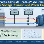
For many alternating-current loads, especially motors and electronic equipment, power factor and efficiency affect the actual input current. Nameplate current is generally more reliable than deriving current from an output-power rating. Three-phase calculations also use a different relationship, commonly involving the square root of three.
🔌 Identify the building’s supply system
Voltage is not just a number printed on a panel door. It determines what equipment can be connected, how loads are balanced, and how current is calculated.
Homes may have a split-phase 120/240 V system. Small commercial buildings may use 120/208 V three-phase service, while other facilities may have 277/480 V systems for larger lighting and mechanical loads. A 208 V appliance is not interchangeable with a 240 V appliance simply because the labels look similar.
Confirm the actual supply from service documentation, panel labels, and qualified testing where necessary. Do not infer it from the building type or from one nearby receptacle.
📋 Build a complete load inventory
The quality of the calculation depends on the inventory. Walk through the building, review drawings and equipment schedules, and ask what will be added after the renovation is complete.
Inventory loads by function and location rather than writing one vague entry such as “office equipment.” Useful categories include general lighting, general-use receptacles, kitchen equipment, HVAC, water heating, pumps, lifts, workshop machinery, IT equipment, and outdoor loads.
For each item, note its quantity, location, voltage, phase, nameplate rating, expected operating pattern, and the panel or feeder that supplies it. A spreadsheet helps because each load may need to appear in more than one subtotal.
🏷️ Use nameplate data whenever equipment exists
An equipment nameplate is often the best starting point because it identifies voltage, current, phase, frequency, and sometimes minimum circuit ampacity or maximum overcurrent protection. These values reflect the equipment as evaluated by its manufacturer.
For fixed appliances and mechanical equipment, record the supplied electrical input rather than assuming a typical value. A heat pump, dishwasher, compressor, or server rack can vary substantially by model and configuration.
If equipment has not yet been selected, use a conservative documented design allowance, then update the calculation when the final equipment schedule is available. Do not quietly replace unknown data with an optimistic guess.
💡 Account for general lighting and receptacle loads
Not every load can be counted device by device. General lighting and general-use receptacles are often calculated using area-based allowances or other methods prescribed by the applicable code, particularly during early design.
These allowances recognize that a building needs usable capacity for ordinary occupancy even before every lamp, desk, or plug-in device is known. They are not necessarily a prediction of metered energy consumption.
As the design matures, actual connected lighting loads and clearly identified utilization equipment may provide better detail where the governing rules permit. The key distinction is that design load is about safe capacity, not an average monthly bill.
🍳 Separate dedicated appliance circuits
Dedicated circuits serve a specific appliance or piece of equipment, such as an oven, garbage disposer, water heater, dishwasher, clothes dryer, or commercial refrigerator. Their load should be identified directly rather than hidden inside a general receptacle allowance.
Check whether the appliance is hardwired or cord-and-plug connected, whether it has a manufacturer-specified circuit requirement, and whether it is expected to operate continuously. Some equipment combines multiple heating elements or motors with internal controls that affect its listed circuit requirements.
Kitchen and laundry areas deserve careful attention because several high-wattage appliances may operate at once. A space can appear modest while imposing a substantial demand on a small panel.
🌡️ Treat heating, cooling, and ventilation as major loads
HVAC equipment is frequently the largest load in a residence and among the largest in commercial spaces. Inventory compressors, air handlers, electric resistance heat, condensing units, exhaust fans, ventilation units, pumps, and controls.
Use the equipment’s electrical data and applicable HVAC calculation rules. Motor-compressor equipment may specify minimum circuit ampacity and a maximum fuse or breaker rating; these values must not be treated as interchangeable.
Heating and cooling that cannot reasonably operate together at full load may be treated differently from additive loads under some rules. However, an all-electric building, heat-pump auxiliary heat, or multiple independently controlled zones can complicate that assumption. Analyze the actual control sequence and the governing code method.
🔄 Distinguish connected load from calculated demand
Connected load is the total rating of equipment connected to a system. Calculated demand is the load used to size a service or feeder after applying permitted rules for simultaneity, diversity, and specific equipment types.
Imagine ten identical office printers that are all plugged in. Adding every nameplate maximum may be far more than their likely simultaneous operation, but assuming only one will ever run could be unsafe. Demand rules provide a structured middle ground.
Never invent a demand factor because a load “usually seems low.” Use the method required by the authority having jurisdiction, project specifications, and the applicable edition of the electrical code.
📉 Apply demand factors only where they are allowed
A demand factor reduces a connected load to a calculated demand under defined conditions. It is based on a recognized calculation procedure, not a general permission to shrink numbers until the service fits.
Demand factors may apply differently to dwelling loads, certain cooking equipment, general lighting, receptacles, or groups of appliances. Their exact values and eligibility depend on the governing standard and the type of occupancy.
Document the original connected load, the rule applied, and the resulting demand. This makes the calculation reviewable and prevents a future designer from mistaking a reduced demand value for the equipment’s actual rating.
⏱️ Recognize continuous loads
A continuous load is generally one expected to operate at its maximum current for a prolonged period, often defined by code as three hours or more. Examples can include certain lighting, EV charging, heating, or process loads, depending on how they are used and regulated.
Continuous loading matters because conductors, terminals, and breakers generate heat over time. The design rules may require the load to be calculated at a higher value or require equipment specifically rated for continuous operation.
Do not label a load continuous merely because it is installed permanently, and do not assume a plug-in load is noncontinuous. The expected duty cycle and applicable rules control the classification.
🧲 Handle motors and compressors correctly
Motors draw a high starting current for a brief period and a lower running current after they reach speed. Circuit conductors and overload protection must support normal operation, while short-circuit and ground-fault protection must tolerate starting without compromising fault protection.
For feeders with multiple motors, calculation methods often require special treatment of the largest motor in addition to the other motor loads. This reflects the possibility that one motor is starting while others are already running.
Use the code tables and equipment instructions applicable to motor circuits. Simply adding breaker handle ratings is not a valid motor-load calculation.
🧮 Calculate at each level of the system
Work from the leaves of the system toward the source. First calculate branch circuits, then each subpanel feeder, then the main service. This approach makes omissions and double counting easier to find.
A load can appear at more than one level, but it should be counted once within each level’s total. For instance, an air conditioner belongs in its branch-circuit calculation, in the panel feeder calculation, and in the service calculation, but not twice in the same panel total.
Maintain separate subtotals for each panel. A building can have adequate overall service capacity while one heavily used subpanel feeder is overloaded.
⚖️ Balance loads across phases and legs
Multiwire and multi-phase systems perform best when loads are distributed reasonably evenly. In a split-phase service, 120 V loads should be spread across both legs. In a three-phase system, single-phase loads should be spread among all phases.
Imbalance increases current in some conductors while leaving others lightly loaded. In systems with substantial nonlinear electronic loads, neutral current also requires thoughtful evaluation because harmonic currents may not cancel as simple arithmetic suggests.
Perfect balance is rarely practical. The goal is a deliberate arrangement based on substantial, likely simultaneous loads, followed by verification during commissioning or operation where appropriate.
🧷 Size conductors from ampacity, not appearance
Conductor size is selected from its allowable ampacity after considering the installation conditions. Wire that looks physically large may still be unsuitable if insulation temperature rating, terminal rating, bundling, ambient temperature, or enclosure conditions reduce its usable ampacity.
Use the approved ampacity tables and the temperature limitations of connected terminals and equipment. The conductor, termination, breaker, and equipment all form one thermal system; the weakest applicable rating can govern.
Voltage drop is a separate design consideration. A conductor can meet minimum ampacity yet still be too small for good equipment performance over a long run.
🌡️ Apply temperature and bundling corrections
Conductors installed in hot spaces, rooftop raceways, crowded cable trays, or conduits with many current-carrying conductors may require ampacity adjustment or correction. Heat from the environment and neighboring conductors limits how effectively insulation can shed heat.
These adjustments are easy to miss when calculations focus only on panel ratings. They can become decisive in commercial retrofits where a new circuit is added to an already crowded pathway.
Record the installation assumptions: conductor type, raceway or cable method, number of current-carrying conductors, ambient conditions, and terminal ratings. If the routing changes in the field, revisit the calculation.
📏 Check voltage drop on long runs
Voltage drop is the reduction in voltage along a conductor caused by its resistance and impedance. Excessive drop can make motors run poorly, dim lighting, reduce heating output, or cause electronic equipment to behave unpredictably.
Long detached garages, agricultural buildings, parking-lot equipment, and remote mechanical units are common trouble spots. Increasing conductor size may reduce voltage drop even when the original conductor size is thermally adequate.
Recommended voltage-drop targets are often design guidance rather than universal code mandates, so verify local requirements and project criteria. Evaluate both the branch circuit and the feeder; their combined effect matters at the load.
🛡️ Coordinate breakers, fuses, and equipment ratings
Overcurrent protective devices are selected to protect conductors and equipment from overloads and faults. They are not simply chosen to be as large as possible without nuisance tripping.
For ordinary loads, breaker sizing follows the calculated load and conductor ampacity under the applicable rules. Motors, HVAC equipment, and some listed appliances have special provisions because normal startup and operating characteristics differ from resistive loads.
Verify interrupting ratings as well as ampere ratings. A breaker must be capable of safely interrupting the available fault current at its point of installation, which can be higher near a transformer or service entrance.
🚨 Do not confuse load calculation with fault analysis
Load calculation determines the expected current during normal use. Short-circuit and coordination analysis addresses the much larger current that may flow during an electrical fault.
Both matter for safe design, but they answer different questions. A panel can have sufficient calculated load capacity while its new breaker has an inadequate interrupting rating for the available fault current.
Larger commercial, industrial, healthcare, and critical facilities often require more formal studies. Even in small projects, confirm that available fault current information, equipment ratings, and protective devices are compatible.
🧰 Verify panel capacity beyond the main breaker
A panel has several practical limits: its bus rating, main breaker rating if present, feeder rating, branch breaker spaces, physical wiring space, and terminal capacity. A vacant slot does not establish capacity for a new load.
Inspect for signs of aging or poor condition, such as corrosion, overheating discoloration, damaged insulation, incompatible breakers, missing dead fronts, or unapproved double-tapped terminals. These conditions need correction independently of the arithmetic.
Also confirm the panel’s listing and manufacturer compatibility. Installing an unapproved breaker type can create a safety and compliance issue even if its ampere rating appears correct.
🔋 Include emerging and intermittent loads realistically
EV chargers, battery energy storage, rooftop solar inverters, induction cooking, heat pumps, and home-office equipment can change a building’s electrical profile quickly. Some are optional today but likely to become routine during the building’s useful life.
An EV charging load may run for hours and can materially affect a service calculation. Solar generation does not automatically cancel a building’s load for conductor and equipment sizing; interconnection, backfeed, and production conditions have their own design rules.
Plan pathways, panel space, and capacity for credible future loads. Avoid paying now for speculative capacity with no design basis, but do not make expansion impossible when a modest allowance would prevent disruptive rework.
🧱 Consider special locations and occupancy needs
Bathrooms, kitchens, outdoors, wet areas, garages, healthcare spaces, hazardous locations, and assembly occupancies can have requirements beyond basic load capacity. Protection methods, wiring methods, equipment ratings, emergency systems, and receptacle placement may change.
A load calculation does not authorize equipment in an unsuitable environment. For example, outdoor equipment may need weather suitability, and combustible dust or flammable-vapor areas may require specially classified electrical systems.
Identify these conditions early. Moving a load from a dry utility room to a wet process area can change far more than the length of the circuit.
🗂️ Use a transparent calculation worksheet
A reliable worksheet lets another qualified person see how every result was produced. It should have enough detail to be checked without reopening every drawing or revisiting the site.
| Worksheet field | Why it belongs in the record |
|---|---|
| Load description and location | Prevents omissions and identifies the supplied area or equipment. |
| Voltage, phase, and nameplate data | Supports correct current calculations and equipment matching. |
| Connected load and demand rule | Shows how the calculated demand was derived. |
| Continuous-load treatment | Documents an important sizing assumption. |
| Panel, feeder, and circuit identification | Connects the calculation to the distribution diagram. |
| Conductor and protection selection | Allows a reviewer to verify the final design decision. |
Date the worksheet and retain the equipment schedules used. Revisions are normal; undocumented revisions are where mistakes persist.
🔍 Perform a field survey before finalizing assumptions
Drawings can be outdated, panels can be relabeled inaccurately, and equipment can be replaced without documentation. A field survey compares the paper design with the building that actually exists.
Photograph nameplates where permitted, trace major feeders, identify panel schedules, and note inaccessible or uncertain items for follow-up. Qualified electrical workers may use measurements to support troubleshooting, but a spot measurement is not automatically a code-compliant demand calculation.
Never rely on a clamp-meter reading taken at a quiet time as proof that a feeder has ample capacity. It captures a moment, not necessarily the worst credible operating condition.
🧪 Test assumptions with operating scenarios
After making the inventory, ask what combinations can operate together. Consider a hot afternoon with cooling equipment running, a morning when kitchen appliances are active, or a winter condition where heat-pump auxiliary heat may energize.
For a hypothetical small clinic, the normal daytime scenario might include lighting, computers, refrigeration, ventilation, and one procedure-room device. A different scenario may include cleaning equipment after hours while HVAC still operates. Each case helps reveal loads that a simple room-by-room list hides.
Scenario thinking does not replace prescribed calculation methods. It improves the input data and helps identify operational conflicts that may require load management.
🚫 Avoid the most common calculation mistakes
Most problems arise from shortcuts, not difficult mathematics. A careful review should specifically look for these patterns:
- Using breaker ratings as if they were the actual connected load.
- Forgetting loads supplied from a subpanel when calculating its feeder.
- Double-counting a load in one total after transferring it from a schedule.
- Applying a demand factor to a load category where it is not permitted.
- Ignoring continuous-duty treatment for charging, lighting, or heating loads.
- Assuming heating and cooling are noncoincident without checking controls and operating modes.
- Selecting conductor size without adjustment factors, terminal limits, or voltage-drop review.
- Confusing unused breaker spaces with available ampere capacity.
👷 Know when professional review is essential
A simple, well-documented project may be within the routine work of a qualified electrician, but complexity rises quickly with service upgrades, multi-tenant buildings, commercial kitchens, generators, solar systems, battery storage, EV infrastructure, motors, or changes to occupancy.
Permits and inspections commonly require calculations prepared or reviewed by appropriately qualified people. Utilities may also impose requirements for service changes, metering, transformer capacity, or distributed generation.
When safety, compliance, or business continuity is at stake, engage the licensed professional required in your jurisdiction. Their role is not merely to sign paperwork; it is to validate assumptions and integrate the calculation with the complete electrical design.
✅ Review the result before construction begins
Before ordering equipment, compare the calculated results against every relevant rating: service conductors, main disconnect, panel bus, feeder conductors, breaker ratings, and equipment instructions. Verify that all values refer to the same voltage system and design condition.
Then check constructability. Can conductors fit in the raceway? Is there workable space in the panel? Are disconnects accessible? Has the design preserved required working clearances? A calculation that cannot be installed safely is unfinished.
Finally, coordinate the updated panel schedules, one-line diagram, equipment schedule, and permit documents. Consistent records reduce errors during installation and later maintenance.
🧠 Build safety into the method, not just the final number
A safe electrical load calculation is a chain of traceable decisions: identify every credible load, classify it correctly, apply only permitted calculation rules, and verify that conductors and protective devices suit the real installation.
The central principle is simple: size the electrical system for the calculated conditions it may actually experience, not for a hopeful average or an empty breaker space. That principle supports reliable operation, future maintenance, and informed decisions when the building changes.
Careful load calculations turn a collection of appliances and circuits into a coordinated electrical system with defensible capacity and clear safety margins. Start with accurate information, document each assumption, and bring in qualified local expertise whenever the design moves beyond a straightforward installation. ⚡🛡️🏢