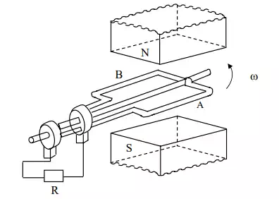
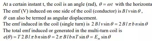
Schematic diagram for single phase ac generation
Schematic diagram for single phase ac generation A multi-turn coil is placed inside a magnet with an air gap as shown in above Fig.. The flux lines are from North Pole to South Pole. The coil is rotated at an angular speed, ω = 2π n (rad/s).

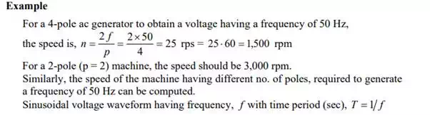
N = 60 n = speed of the coil (rev/min, or rpm)
l = length of the coil (m)
b = width (diameter) of the coil (m)
T = No. of turns in the coil
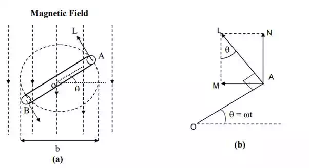
(a) Coil position for Fig, and (b) Details
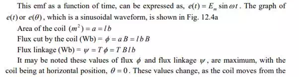
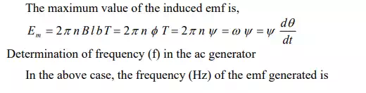
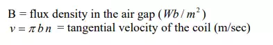
horizontal position. So, also is the value of induced emf as stated earlier. The maximum value of the induced emf is,